00195722-0102_UM_X-Serie_SR605_EN.pdf - 第316页
4 Setting up and commissioning User Manual SIPLACE X-Series 4.6 Adapting the used tape channel From software version SR.605.xx 07/2008 EN Edition 316 4.6.1.1 Safety instructions WA R N I N G 4 → Switch the placement mach…
User Manual SIPLACE X-Series 4 Setting up and commissioning
From software version SR.605.xx 07/2008 EN Edition 4.6 Adapting the used tape channel
315
4.5.1.3 Setting the used tape chute to PCB conveyor heights of 900 mm - 950 mm
→ Loosen the two M4 hexagonal nuts (item 3 in Fig. 4.5 - 1, page 314).
→ Adjust the extension (item 2 in Fig. 4.5 - 1
, page 314) so that the distance between the bottom
edge and the floor does not exceed 320 mm + 20 mm (see Fig. 4.5 - 1
, page 314).
4.6 Adapting the used tape channel
4.6.1 Adapting the SIPLACE X-series used tape channel to the component height
If X feeder modules are used, the component tapes work with a pocket height > 12 mm, so the
separating plate (item 1 in Fig. 4.6 - 1
) must be removed.
4
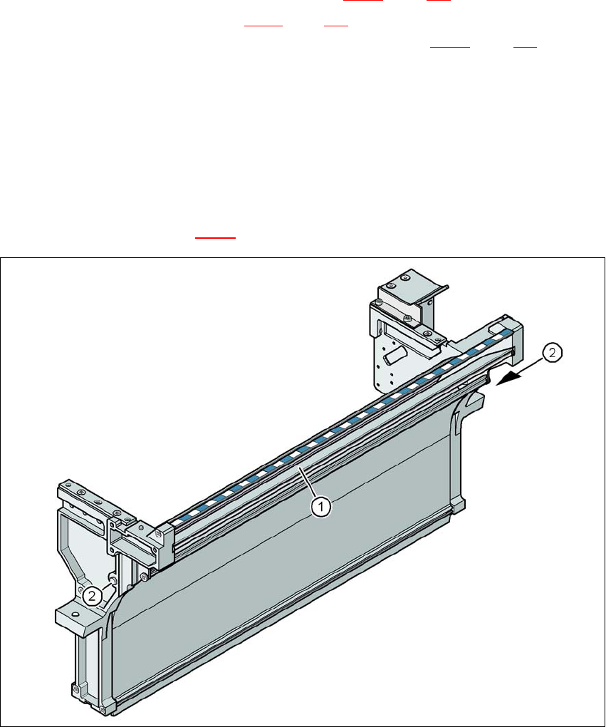
Fig. 4.6 - 1 Used tape channel, SIPLACE X-series
(1) Separating plate for tapes > 12 mm, removable
(2) DIN 93384 screw - M4x20, 2x
4 Setting up and commissioning User Manual SIPLACE X-Series
4.6 Adapting the used tape channel From software version SR.605.xx 07/2008 EN Edition
316
4.6.1.1 Safety instructions
WARNING 4
→ Switch the placement machine off at the main switch to remove the dividing plate.
→ Disconnect the machine from the power and compressed air supply.
→ Secure the machine to prevent it being switched on again, as described in Section 2.10
, page
96
.
→ Wait until the operating pressure for the tape cutter has dropped to 0 MPa.
→ Do not reach inside the used tape channel.
4.6.1.2 Removing the separating plate
→ Loosen the two hexagon head screws (item 2 in Fig. 4.6 - 1, page 315).
→ Pull out the separating plate (item 1 in Fig. 4.6 - 1
, page 315).
4.6.2 Adapting the SIPLACE HF used tape channel to the component height
If S feeder modules that process component tapes with a pocket height > 17 mm are used, such
as, for example, the 44 mm S DP feeder module, then the separating plate (item 1 in Fig. 4.6 - 2
,
page 317
) must be removed.
4.6.2.1 Safety instructions
WARNING 4
→ Switch the placement machine off at the main switch to remove the dividing plate.
→ Disconnect the machine from the power and compressed air supply.
→ Secure the machine to prevent it being switched on again, as described in Section 2.10
, page
96
.
→ Wait until the operating pressure for the tape cutter has dropped to 0 MPa.
→ Wear robust protective gloves.
→ Do not reach inside the used tape channel.
User Manual SIPLACE X-Series 4 Setting up and commissioning
From software version SR.605.xx 07/2008 EN Edition 4.6 Adapting the used tape channel
317
4
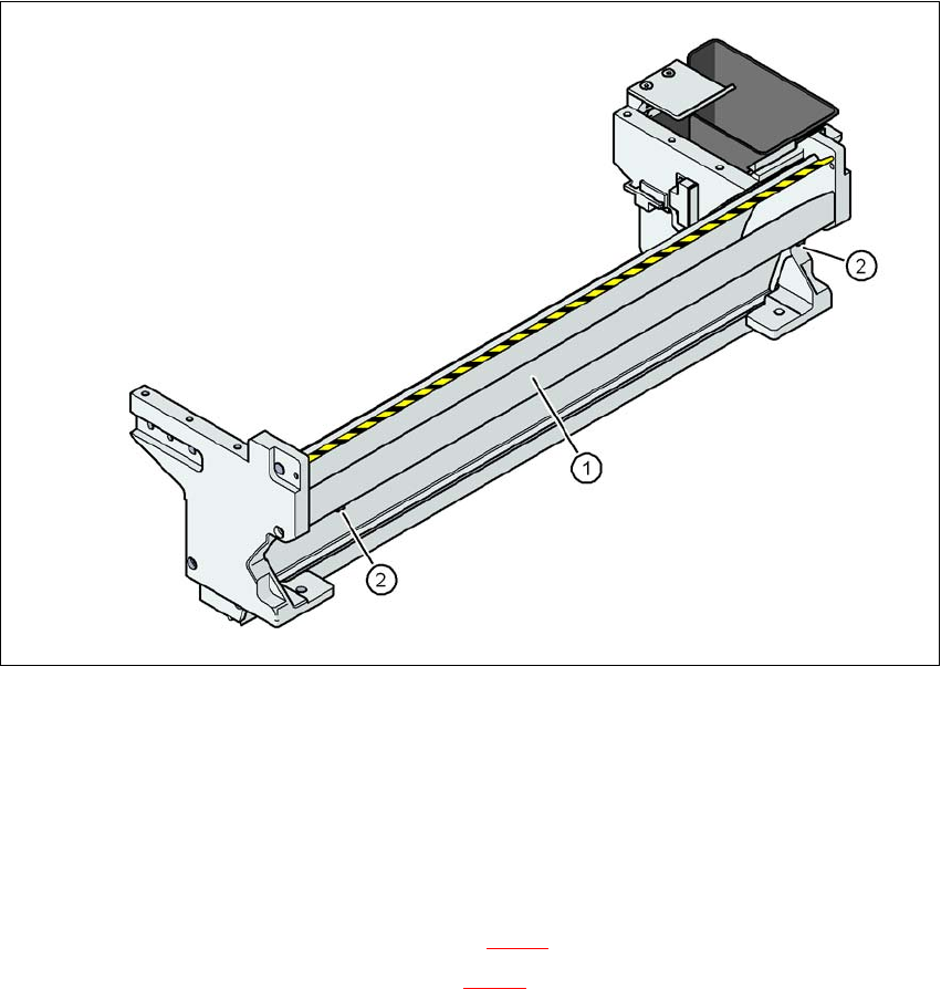
Fig. 4.6 - 2 Used tape channel with component reject bin
(1) Separating plate for tapes > 17 mm, removable
(2) DIN 84 - M3x6 screw, 2x
4
4
4.6.2.2 Removing the separating plate
→ Loosen the two slotted screws (item 2 in Fig. 4.6 - 2).
→ Pull out the separating plate (item 1 in Fig. 4.6 - 2
).