00195722-0102_UM_X-Serie_SR605_EN.pdf - 第234页
3 Technical data for the machine User Manual SIPLACE X-Series 3.12 SIPLACE HF component trolley From software ver sion SR.605.xx 07/2008 EN Edition 234 3.12.9 Feeder module fixing, SI PLACE HF component trolley Item no. …
User Manual SIPLACE X-Series 3 Technical data for the machine
From software version SR.605.xx 07/2008 EN Edition 3.12 SIPLACE HF component trolley
233
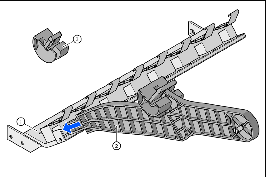
3.12.8 Mount for the middle tape reel on 3 x 8 mm S feeder modules
Item no. 00119643-xx Adapter plate, component trolley, HF/X/D3
Item no. 00141204-xx Tape reel holder, feeder module 3 x 8 mm, V2
Type 3 x 8 mm S feeder modules transport components to the pick-up position on three feeder
tracks. The tape reels of the two outer tracks are positioned between the separating plates in the
tape container. The middle tape reel is arranged over the tape reels for the two outer tracks.
For the middle tape reels you will therefore also need:
– 1 adapter plate for holding the tape reel holder (item 1),
– for every two feeder modules, 1 tape reel holder (item 2) and
– 1 shortened idler pulley (item 3) for the tape reel holder at location 1 of the component table.
The adapter plate is fixed inside the component trolley with four fillister head screws, and the tape
reel holders are inserted into the square openings in the adapter plate.
3
Fig. 3.12 - 7 Mount for the middle tape reel on 3 x 8 mm S feeder modules
3
(1) Adapter plate
(2) Tape reel holder
(3) Idler pulley, shortened
3 Technical data for the machine User Manual SIPLACE X-Series
3.12 SIPLACE HF component trolley From software version SR.605.xx 07/2008 EN Edition
234
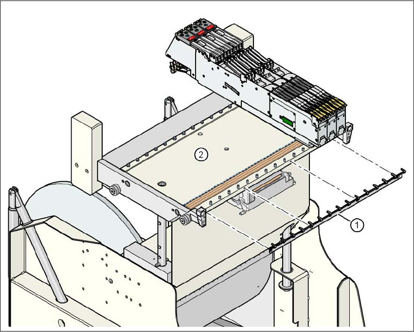
3.12.9 Feeder module fixing, SIPLACE HF component trolley
Item no. 00119623-xxFeeder module fixing, SIPLACE HF/X/D3
The feeder module fixing is an additional mechanical locking device. It prevents the feeder mod-
ules accidentally moving on the component table and thus prevents the risk of collision with the
placement head.
The feeder module fixing is fixed to the front panel of the component table using screws. The claws
fix the feeder module feet. One feeder module fixing is needed for each component trolley.
3
Fig. 3.12 - 8 Feeder module fixing, SIPLACE HF component trolleys
3
(1) Feeder module fixing
(2) Component table
User Manual SIPLACE X-Series 3 Technical data for the machine
From software version SR.605.xx 07/2008 EN Edition 3.12 SIPLACE HF component trolley
235
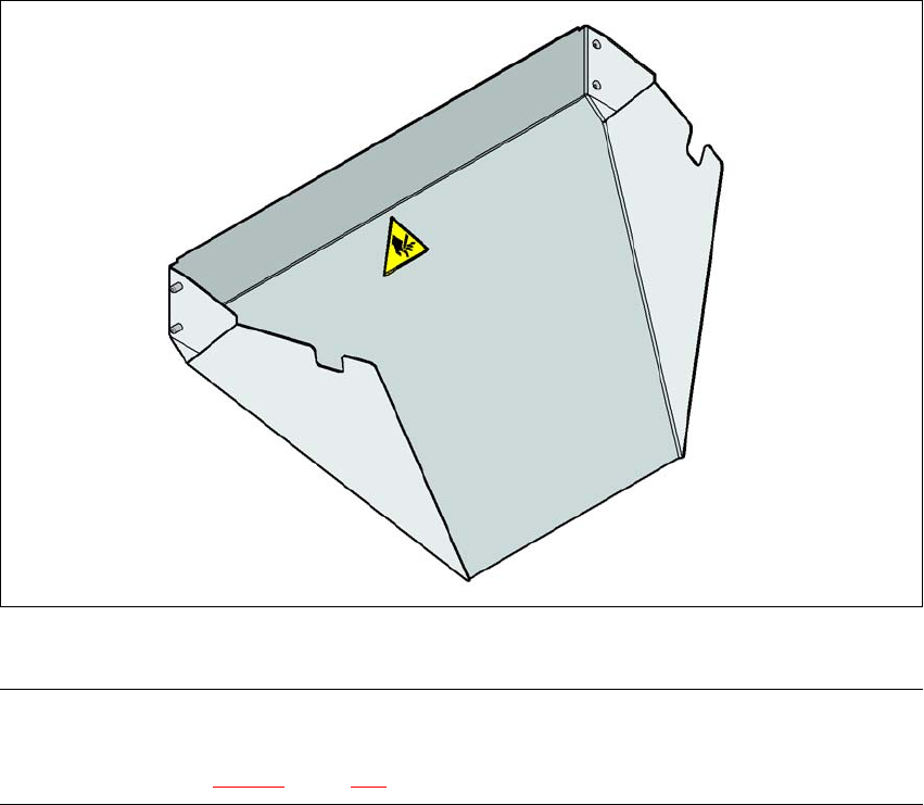
3.12.10 Used tape chute, SIPLACE HF
3
Fig. 3.12 - 9 Used tape chute for SIPLACE HF
PLEASE NOTE 3
The SIPLACE HF used tape chute can only be installed on the SIPLACE HF component trolley
docking unit (see Fig. 5.11 - 6, page 364.