00195722-0102_UM_X-Serie_SR605_EN.pdf - 第147页
User Manual SIPLACE X-Series 3 Technical data for the machine From software version SR.605.xx 07/2008 EN Edition 3.7 PCB conveyor system 147 veying time of one PCB, thus considerably incr ea sing performance, p artic ula…
3 Technical data for the machine User Manual SIPLACE X-Series
3.7 PCB conveyor system From software version SR.605.xx 07/2008 EN Edition
146
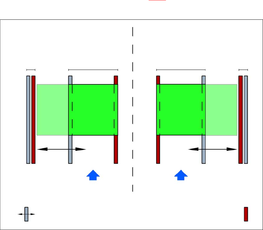
3.7.3.4 Dual conveyor in Single conveyor mode
The dual conveyor can be configured online to create a single conveyor. To do this, one conveyor
track is moved fully together and deactivated (see Fig. 3.7 - 3
). This gives a conveyor track width
of up to 450 mm.
3
Fig. 3.7 - 3 Flexible dual conveyor in Single conveyor mode
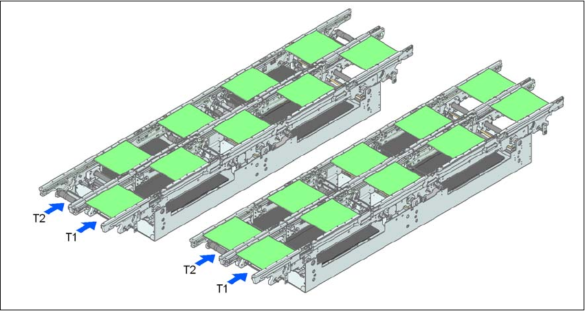
3.7.3.5 Transport modes
The flexible dual conveyor can be used in two modes:
– Synchronous transport mode
– Asynchronous transport mode
3.7.3.6 Asynchronous transport mode
Description 3
In asynchronous mode, only one PCB in a transport track is processed. At the same time, another
PCB in the second transport track is moved into the placement position. This saves the full con-
Dual conveyor with widened conveyor track 2
(stationary conveyor side wall on left)
Conveyor track 2
deactivated
Conveyor track 1 Conveyor track 2 Conveyor track 1
deactivated
PCB transport direction PCB transport direction
Stationary conveyor side wall
Dual conveyor with widened conveyor track 1
(stationary conveyor side wall on right)
Movable conveyor side wall
User Manual SIPLACE X-Series 3 Technical data for the machine
From software version SR.605.xx 07/2008 EN Edition 3.7 PCB conveyor system
147
veying time of one PCB, thus considerably increasing performance, particularly for PCBs with a
short cycle time.
Once the machine has received the job data (panel, set-up), the PCBs on the feeding belts are
continuously transported to the available processing belt (provided that the processing belt is free)
throughout the placement operation. The placement sequence starts as soon as a PCB has
moved onto the processing belt. The PCBs are processed one after another.
If the placement sequence is interrupted, the conveyor interface will be disabled and the PCBs
currently on the processing belts will be completed.
The conveyor interface is disabled or enabled simultaneously for both transport tracks.
3
Fig. 3.7 - 4 Transport modes
3.7.3.7 Synchronous transport mode
Description 3
In synchronous mode, two PCBs of the same size are moved into the placement position at the
same time. They must be processed as a common panel.
In this way, the top and bottom of a PCB can be processed on a single line, and the time required
to transport the PCB is shorter since two PCBs are always transported at the same time. It also
ensures better utilization of the nozzle configuration.
Synchronous transport modeAsynchronous transport mode

3 Technical data for the machine User Manual SIPLACE X-Series
3.7 PCB conveyor system From software version SR.605.xx 07/2008 EN Edition
148
PCBs on conveyor tracks 1 and 2 are moved synchronously onto the conveyor sections (i.e. the
conveyors are controlled synchronously, but independently of one another). The components to
be placed on conveyor tracks 1 and 2 must be organized into a panel via two subpanels. (See the
SIPLACE Pro user manual).
If only one conveyor track (or center conveyor) is full when the placement sequence starts, the
subpanel on this section will be identified as “not for placement”.
If the dual conveyor is operated in synchronous mode, the ‘PCB whispering down the line’ option
is deactivated. PCB barcode operation is not supported in this mode. The "Global bad fiducial"
option cannot be used.
3.7.4 Controlling and width adjustment
3.7.4.1 Controlling using the Single Functions menu
The online help contains information on controlling the PCB conveyor system and on the Single
Functions menu.
3.7.4.2 Automatic width adjustment
When the command is received, the conveyor belts are set to the desired width. Different widths
are possible for a dual conveyor.
See the Online Help for detailed information about changing the conveyor track width.
3.7.5 Technical data
3.7.5.1 Technical data for a PCB single conveyor
3
Fixed conveyor side Right or left
PCB formats
Maximum dimensions (length x width)
a
Standard (length x width)
Wide board configuration
Conveyor width 21 configuration
Long board option
b
Long board option and
Wide board configuration
685 x 610 mm²
50 x 50 mm² to 450 x 460 mm²
c
50 x 50 mm² to 450 x 508 mm²
c
50 x 50 mm² to 450 x 533 mm²
c
50 x 80 mm² to 610 x 460 mm²
c
50 x 80 mm² to 610 x 508 mm²
c
PCB thickness
Standard 0.3 mm to 4.5 mm ± 0.2 mm
(thicker PCBs available on request)
PCB warpage see Section 3.7.7
, page 151
PCB weight max. 3 kg