00195722-0102_UM_X-Serie_SR605_EN.pdf - 第365页
User Manual SIPLACE X-Series 5 Tasks for the operating personnel From software version SR.605.xx 07/2008 EN Edition 5.11 Docking the component trolley in or out 365 CAUTION 5 Check that the placement he ad is outside the…
5 Tasks for the operating personnel User Manual SIPLACE X-Series
5.11 Docking the component trolley in or out From software version SR.605.xx 07/2008 EN Edition
364
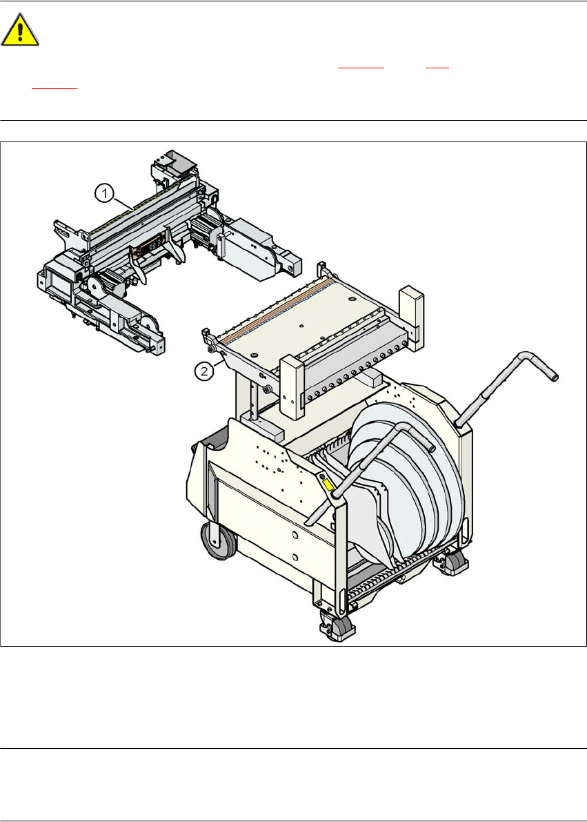
5.11.6 Docking the HF component trolley
CAUTION 5
The component trolleys for the SIPLACE X-series (Fig. 5.11 - 3
, page 360) and SIPLACE HF
(Fig. 5.11 - 6
) have different docking units. Each component trolley must therefore only be
docked into the correct docking unit.
5
Fig. 5.11 - 6 Component trolley and component trolley docking unit, SIPLACE HF
(1) Component trolley docking unit, SIPLACE HF
(2) Component trolley, SIPLACE HF
PLEASE NOTE 5
Shorten the component tapes on the front end of the S feeder modules to approximately 1 cm
before you dock in the HF-series component trolley.
User Manual SIPLACE X-Series 5 Tasks for the operating personnel
From software version SR.605.xx 07/2008 EN Edition 5.11 Docking the component trolley in or out
365
CAUTION 5
Check that the placement head is outside the range of the component trolley.
→ Carefully push the component trolley into machine as far as the stop.
PLEASE NOTE 5
Close the protective covers since the component trolley can only be docked in if the covers are
closed.
→ Press the relevant button on the input or output side of the machine (item 1, 2, 3 or 4 in Fig.
5.11 - 1
, page 358), until the trolley is docked in fully.
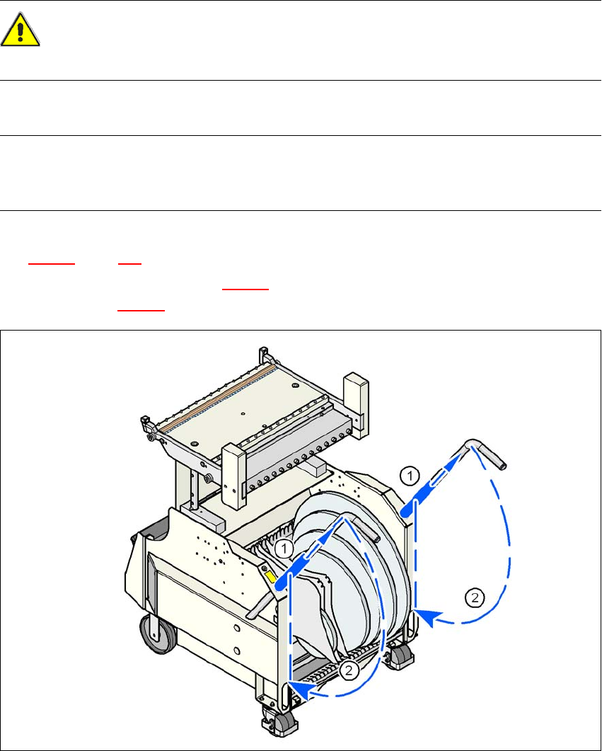
→ Push the sleeve (item 1 in Fig. 5.11 - 7
) up using both handles and swivel the handle down
(item 2 in Fig. 5.11 - 7
).
5
Fig. 5.11 - 7 HF component trolley - swivel handles down
(1) Push sleeve up
(2) Fold handle down
5 Tasks for the operating personnel User Manual SIPLACE X-Series
5.12 Docking the component trolley in or out at the docking station From software version SR.605.xx 07/2008 EN Edition
366
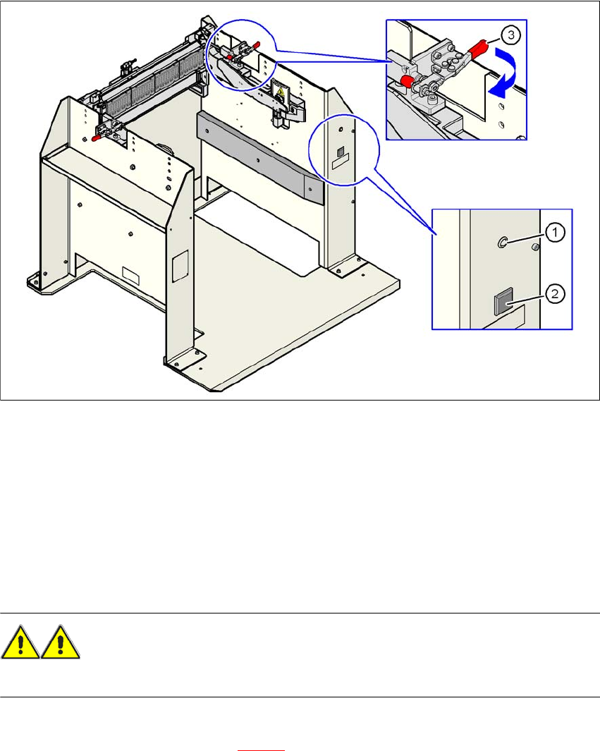
5.12 Docking the component trolley in or out at the
docking station
5
Fig. 5.12 - 1 Component trolley X-series - swivel handles down
(1) Main power supply indicator lamp
(2) Button for locking and releasing all the feeder modules on the component trolley
(3) Horizontal tensioner for fixing the component table lever in the "closed" position
5
5
5.12.1 Docking the SIPLACE X-series component trolley into the docking station
WARNING 5
→ While docking, do not reach into the areas between component trolley and docking station.
→ Release the two horizontal tensioners at the same time by moving them in the direction indi-
cated by the arrow (item 3 in Fig. 5.12 - 1
).