00195722-0102_UM_X-Serie_SR605_EN.pdf - 第212页
3 Technical data for the machine User Manual SIPLACE X-Series 3.10 S feeder modules for the SIPLACE HF component trolley From software version SR.605.xx 07/2008 EN Edition 212 The Dip module is suitable fo r the followin…
User Manual SIPLACE X-Series 3 Technical data for the machine
From software version SR.605.xx 07/2008 EN Edition 3.10 S feeder modules for the SIPLACE HF component trolley
211
3.10.10 Dip module for the SIPLACE HF component trolley
Item no. 00117010-xx Dip module for flux and adhesives
3
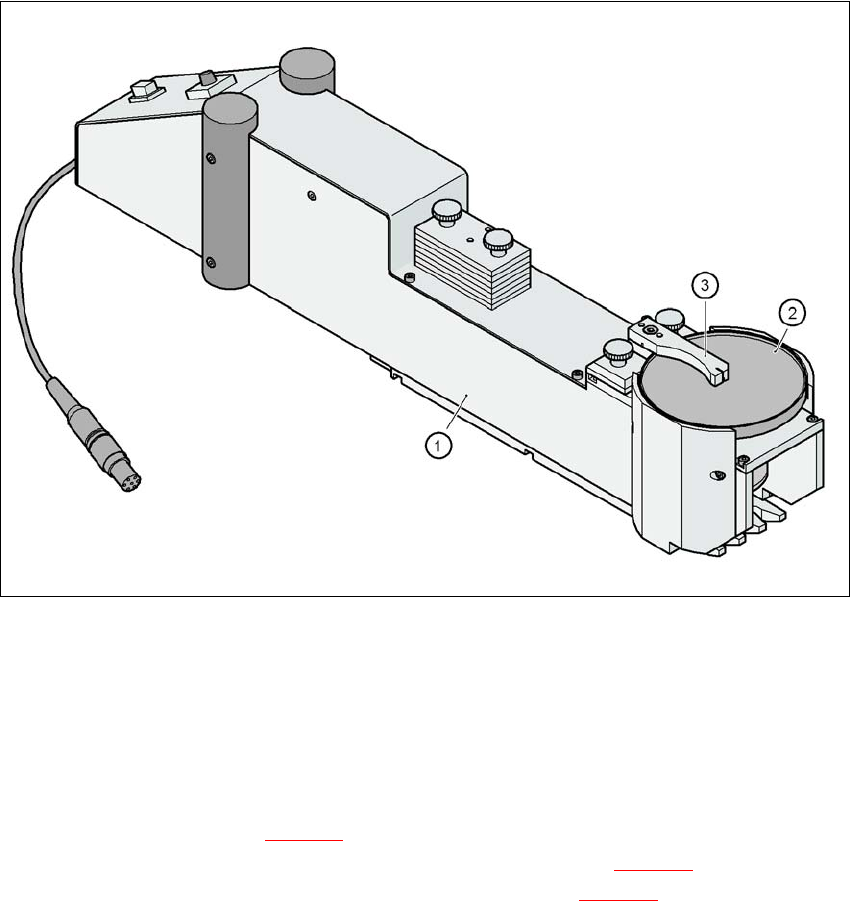
Fig. 3.10 - 18 Dip module
(1) dip module
(2) Rotating plate
(3) Squeegee
3.10.10.1 Description
The dip module (item 1 in Fig. 3.10 - 18) is used to wet flip-chip and CSP components with flux or
conductive adhesive. The flux holder is a rotating plate (item 2 in Fig. 3.10 - 18
) on which a thin
film of flux (e.g. 40 µm) is created with a squeegee (item 3 in Fig. 3.10 - 18
). This method is par-
ticularly suitable for highly viscous (honey-like) fluxes. The amount of flux required for the process
is reduced to a minimum coating thickness since only the undersides of the bumps have to be wet-
ted.
3 Technical data for the machine User Manual SIPLACE X-Series
3.10 S feeder modules for the SIPLACE HF component trolley From software version SR.605.xx 07/2008 EN Edition
212
The Dip module is suitable for the following placement heads:
6-segment Collect&Place head
12-segment Collect&Place head
TwinHead 3
The Dip module is regarded as a separate feeder module type by the set-up optimization. There
is no limit to the number of dip modules at the individual locations.
3.10.10.2 Technical data
Feeder module locations filled 3 3
Component size Max. 36 x 36 mm²
depending on the placement head type 3
Possible coating thicknesses 25, 35, 45, 55, 65, 75 µm 3
Time required to change the coating thickness Less than 1 min. 3
Gap height tolerance ± 5 μm 3
Time for 1 revolution of the table Can be set using the potentiometer from 0 -
10s 3
Component dip time Programmable from 0 - 2s
in 0.1s increments 3
Flux Highly viscous flux, conductive adhesive 3
Further technical data and information on programming can be found in the Betriebsanleitung
DIP-Modul / DIP Module User Manual, item no. 00195065-xx.
3
User Manual SIPLACE X-Series 3 Technical data for the machine
From software version SR.605.xx 07/2008 EN Edition 3.11 SIPLACE X-series component trolley
213
3.11 SIPLACE X-series component trolley
Item no. 00119722-xx CO trolley SIPLACE X-series
Up to four SIPLACE X-series component trolleys can be docked into the machines from the
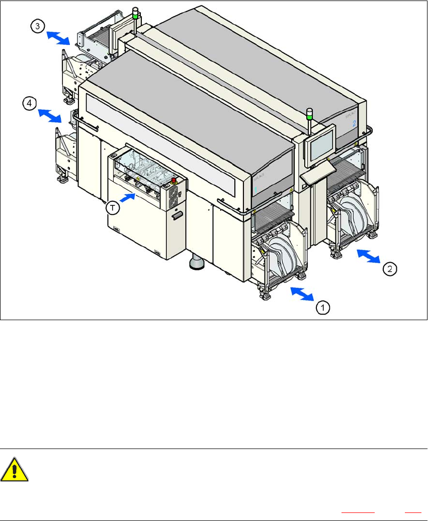
SIPLACE X-series. The locations are numbered as shown in the diagram below.
3
Fig. 3.11 - 1 Component trolley locations, SIPLACE X-series
(1) Location 1
(2) Location 2
(3) Location 3
(4) Location 4
(T) PCB direction of travel
CAUTION 3
The component trolleys from the SIPLACE X-series may only be docked into locations at which
the component trolley docking unit for the SIPLACE X-series is installed (Fig. 5.11 - 3, page 360).