00195722-0102_UM_X-Serie_SR605_EN.pdf - 第400页
6 Station extensions User Manual SIPLACE X-Series 6.1 Nozzle changer From software version SR.605.xx 07/2008 EN Edition 400 6.1.4.5 Position of the nozzle changers for t he T winHead on the X2 machine A nozzle change r m…
User Manual SIPLACE X-Series 6 Station extensions
From software version SR.605.xx 07/2008 EN Edition 6.1 Nozzle changer
399
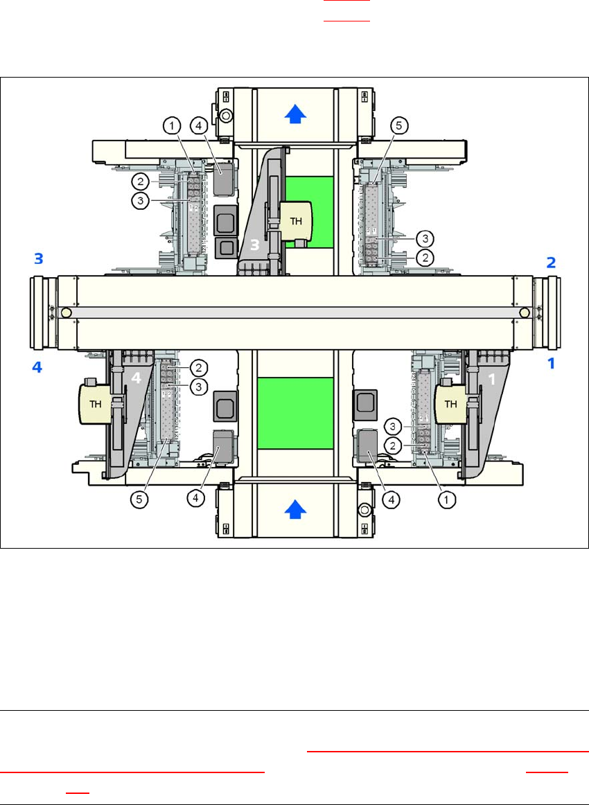
6.1.4.4 Position of the nozzle changers for the TwinHead on the X3 machine
A nozzle changer may be installed for the TwinHead at locations 1 to 4.
Nozzle changer 1 at locations 1 and 3 (item 1 in Fig. 6.1 - 27
): 12 magazines each
Nozzle changer 2 at locations 2 and 4 (item 5 in Fig. 6.1 - 27
): 10 magazines
This gives a total capacity of 4 nozzle changers with 44 magazines and a total of 88 nozzle hold-
ers.
6
Fig. 6.1 - 27 Position of the nozzle changers for the TwinHead on the X3 machine
(1) Nozzle changer 1
(2) Standard magazine
(3) Magazine for special nozzles or grippers
(4) Component reject bin
(5) Nozzle changer 2
PLEASE NOTE 6
If there is an MTC installed at location 4, then the "Nozzle changer for the TwinHead in the place-
ment area with 2 gantries and docked MTC" option must be set up there (see Section 6.1.4.7,
from page 402).
6 Station extensions User Manual SIPLACE X-Series
6.1 Nozzle changer From software version SR.605.xx 07/2008 EN Edition
400
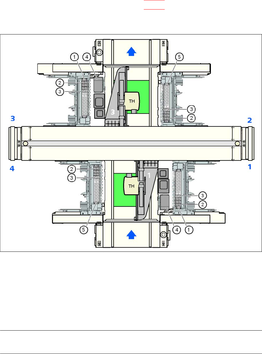
6.1.4.5 Position of the nozzle changers for the TwinHead on the X2 machine
A nozzle changer may be installed for the TwinHead at locations 1 to 4.
Nozzle changer 1 at locations 1 and 3 (item 1 in Fig. 6.1 - 28
) 12 magazines each
Nozzle changer 2 at locations 2 and 4 (item 5 in Fig. 6.1 - 28
): 10 magazines each
This gives a total capacity of 4 nozzle changers with 44 magazines and a total of 88 nozzle hold-
ers.
6
Fig. 6.1 - 28 Position of the nozzle changers for the TwinHead on the X2 machine
(1) Nozzle changer 1
(2) Standard magazine
(3) Magazine for special nozzles or grippers
(4) Component reject bin
(5) Nozzle changer 2
PLEASE NOTE 6
No nozzle changer can be set up at location 4 if there is an MTC installed there.
User Manual SIPLACE X-Series 6 Station extensions
From software version SR.605.xx 07/2008 EN Edition 6.1 Nozzle changer
401
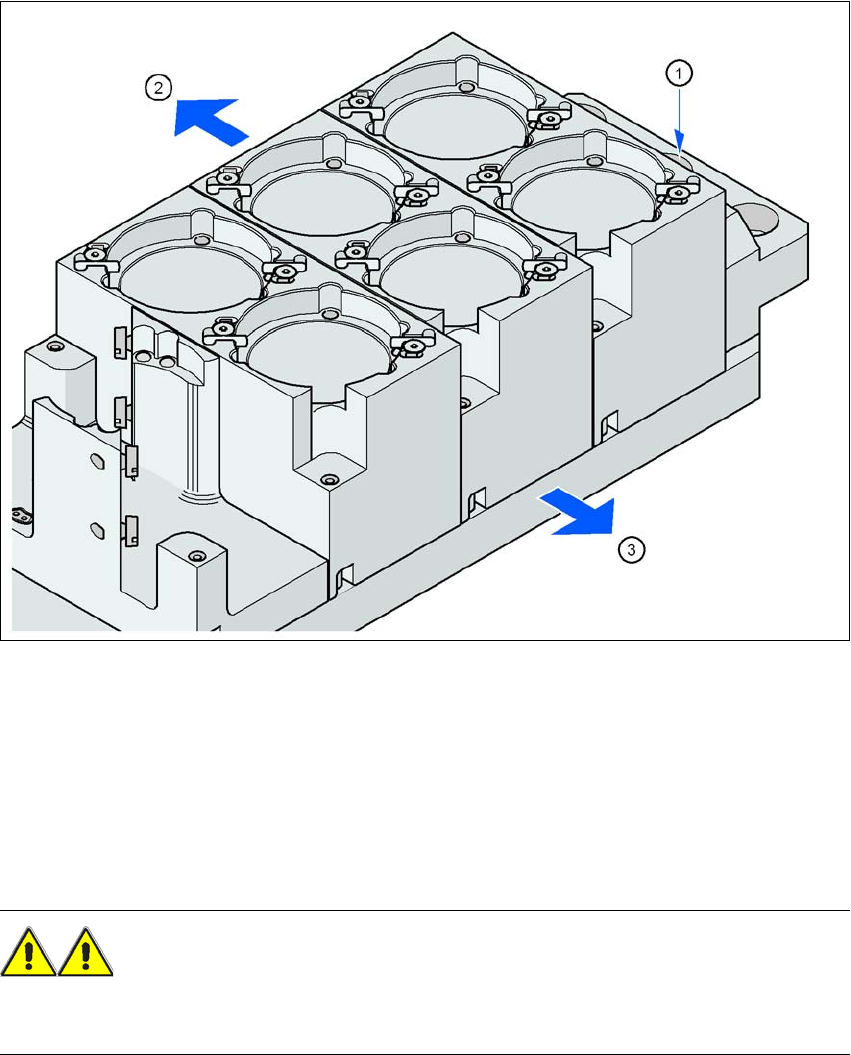
6.1.4.6 Assembly
The nozzle changer is fixed to the component trolley docking unit.
6
Fig. 6.1 - 29 Assembly position
(1) Marking hole
(2) Operator side
(3) Arrow pointing toward the PCB conveyor
6
→ Align the nozzle changer so that the marking hole (item 1) is on the left, as viewed by the op-
erator.
WARNING 6
Only install the associated nozzle changer for each placement head. There is a risk of head
crashes with mixed configurations.