00195722-0102_UM_X-Serie_SR605_EN.pdf - 第314页
4 Setting up and commissioning User Manual SIPLACE X-Series 4.5 Adapting the used tape chute to the PCB conveyor hei ght From software version SR.605.xx 07/200 8 EN Edition 314 4.5 Adapting the used t ape chute to the PC…
User Manual SIPLACE X-Series 4 Setting up and commissioning
From software version SR.605.xx 07/2008 EN Edition 4.4 Adapting the component trolley to the PCB conveyor height
313
4
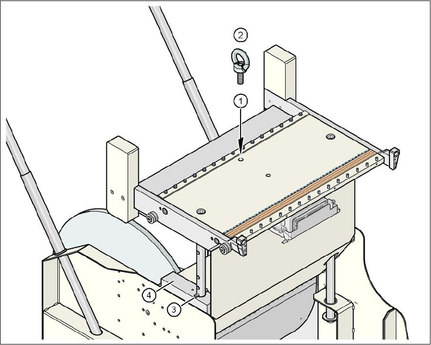
Fig. 4.4 - 4 Positions of the eye-bolt on the SIPLACE HF component trolley
(1) M12 hole for eye-bolt
(2) Eye-bolt, DIN 580 M12-St
(3) Spiral clamping pin, DIN 7343, 8x40 - St, 2x
(4) Supporting block, 2x
4 Setting up and commissioning User Manual SIPLACE X-Series
4.5 Adapting the used tape chute to the PCB conveyor height From software version SR.605.xx 07/2008 EN Edition
314
4.5 Adapting the used tape chute to the PCB conveyor
height
4.5.1 Adapting the SIPLACE X-series used tape chute to the PCB conveyor height
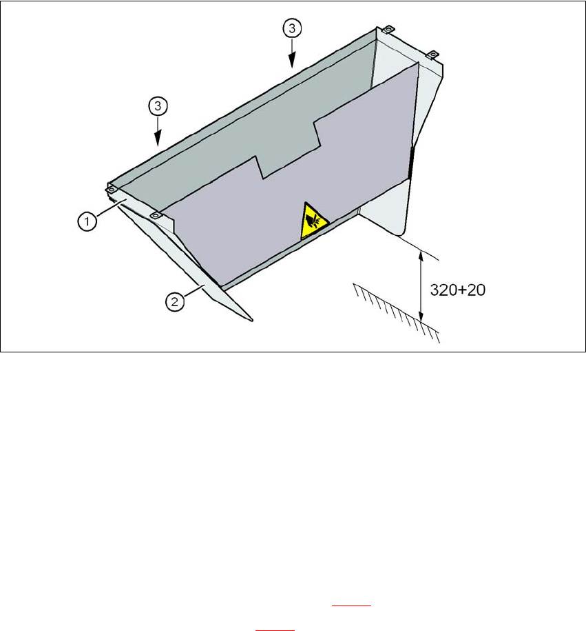
Depending on the PCB conveyor height, the length of the waste tape chute can be set so that the
pieces of tape are diverted directly into the waste tape container of the component trolley.
4
Fig. 4.5 - 1 Adapting the length of the used tape chute (X-series) - Dimensions in millimeters
(1) Used tape chute
(2) Extension
(3) Hexagonal nut M4, DIN 985, 2 x
4.5.1.1 Tools
– Fork wrench, size 7
4.5.1.2 Setting the used tape chute to PCB conveyor height of 830 mm
→ Loosen the two M4 hexagonal nuts (item 3 in Fig. 4.5 - 1).
→ Remove the extension (item 2 in Fig. 4.5 - 1
).
User Manual SIPLACE X-Series 4 Setting up and commissioning
From software version SR.605.xx 07/2008 EN Edition 4.6 Adapting the used tape channel
315
4.5.1.3 Setting the used tape chute to PCB conveyor heights of 900 mm - 950 mm
→ Loosen the two M4 hexagonal nuts (item 3 in Fig. 4.5 - 1, page 314).
→ Adjust the extension (item 2 in Fig. 4.5 - 1
, page 314) so that the distance between the bottom
edge and the floor does not exceed 320 mm + 20 mm (see Fig. 4.5 - 1
, page 314).
4.6 Adapting the used tape channel
4.6.1 Adapting the SIPLACE X-series used tape channel to the component height
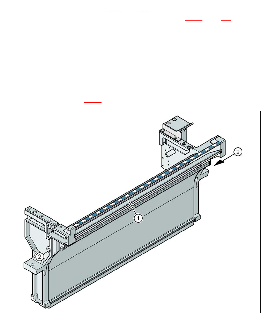
If X feeder modules are used, the component tapes work with a pocket height > 12 mm, so the
separating plate (item 1 in Fig. 4.6 - 1
) must be removed.
4
Fig. 4.6 - 1 Used tape channel, SIPLACE X-series
(1) Separating plate for tapes > 12 mm, removable
(2) DIN 93384 screw - M4x20, 2x