00195722-0102_UM_X-Serie_SR605_EN.pdf - 第270页
4 Setting up and commissioning User Manual SIPLACE X-Series 4.3 Setting up the placement machine From software version SR.605.xx 07/2008 EN Edition 270 4.3.7.5 Fitting the grounding cable for the doors → Fix the two grou…

User Manual SIPLACE X-Series 4 Setting up and commissioning
From software version SR.605.xx 07/2008 EN Edition 4.3 Setting up the placement machine
269
4.3.7.3 Fitting the guide for the hexagonal shaft
→ On the single conveyor, fix one guide for the hexagonal shaft (item 8 in Fig. 4.3 - 7, page 265)
to the extension kit using two fillister head screws M6x16 and washers.
→ On the double conveyor, fix two guides for the hexagonal shaft (item 8 in Fig. 4.3 - 7
, page
265
) to the extension kit using two fillister head screws M6x16 and washers.
4.3.7.4 Producing cable connections - extension kit on the PCB output side
4
4
4
4
4
Left-hand side of the extension kit
(viewed in the direction of travel)
Connector/cable To connector/cable
EMERGENCY STOP button
Start/stop button
X63/03020687 X63/03002526
Protective cover switch, location 3
X53/03020409 X53/03002528
Button for the component trolley docking unit,
location 3
X232/03021056 X232/03021053
Right-hand side of the extension kit
(viewed in the direction of travel)
Connector/cable To connector/cable
Start/stop button
Switch, PCB conveyor cover
X62/03020410 X62/03002525
Protective cover switch, location 2
X52/03006476 X52/03002527
Button for the component trolley docking unit,
location 2
X222/03021056 X222/03021052
4 Setting up and commissioning User Manual SIPLACE X-Series
4.3 Setting up the placement machine From software version SR.605.xx 07/2008 EN Edition
270
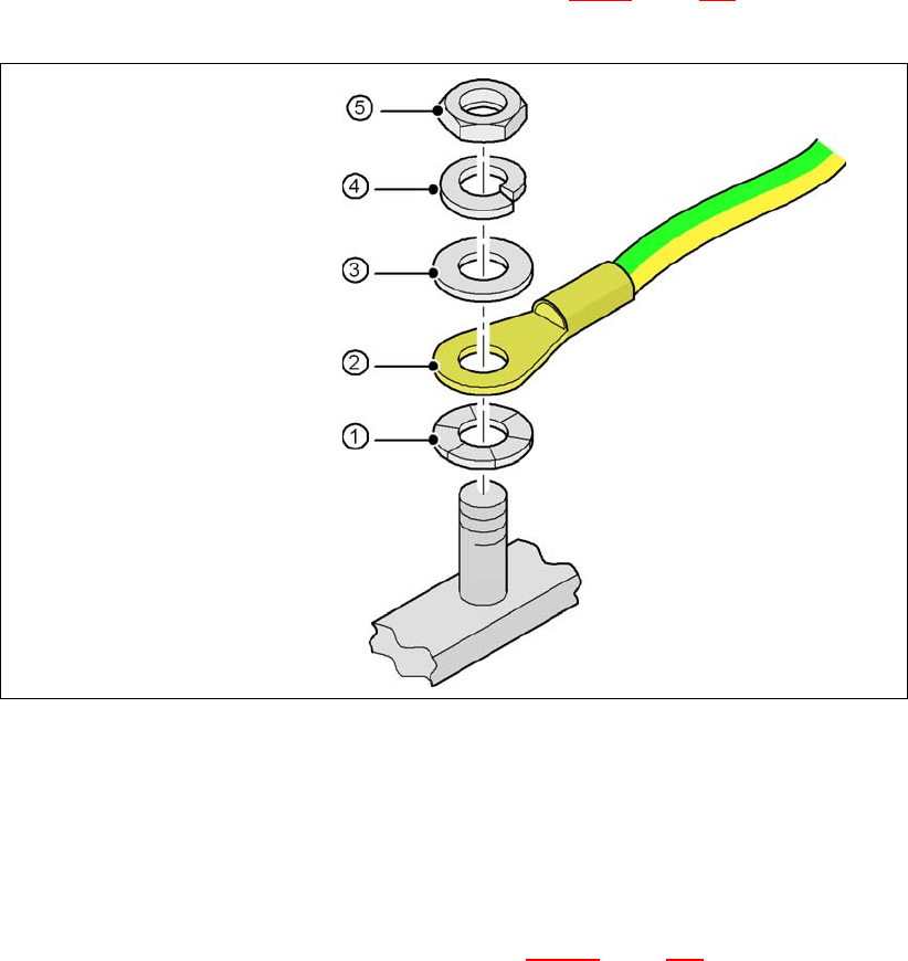
4.3.7.5 Fitting the grounding cable for the doors
→ Fix the two grounding cables for the doors (item 4 in Fig. 4.3 - 8, page 267) to the machine
frame as follows:
4
Fig. 4.3 - 9 Fitting the grounding cable
4
4
4
4
4
4.3.7.6 Checking and setting the protective cover switch
→ Check that the protective cover switch (item 2 in Fig. 4.3 - 17, page 286) is working correctly.
→ Adjust the protective cover switch if necessary (see service manual).
Hex nut M5
Spring washer M5, DIN 7980
Washer M5, DIN 125
Cable lug, annular
Contact washer
User Manual SIPLACE X-Series 4 Setting up and commissioning
From software version SR.605.xx 07/2008 EN Edition 4.3 Setting up the placement machine
271
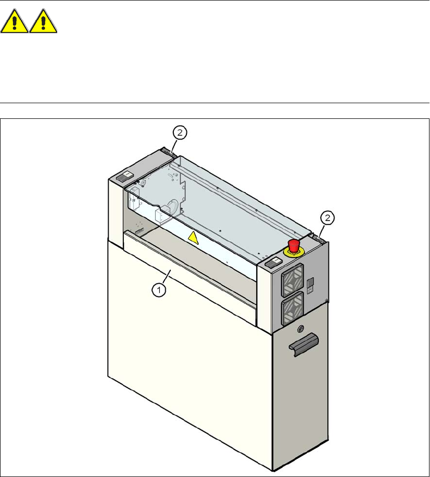
4.3.7.7 Fitting the "bottom" hand guard
The machines are supplied with just one "bottom" hand guard. If the machines are installed within
a line, then no hand guard is required between immediately adjacent output and input conveyors.
WARNING 4
Always fit the "bottom" hand guard (item no. 03045426-xx) on the input side of the first place-
ment machine and on the output side of the last placement machine of a line using 4 hexagon
socket head screws M4x12. This will prevent your personnel reaching into the machine without
authorization.
4
Fig. 4.3 - 10 Fitting the "bottom" hand guard on the PCB output side
(1) "Bottom" hand guard, item no. 03045426-xx
(2) Protective cover switch