00195722-0102_UM_X-Serie_SR605_EN.pdf - 第235页
User Manual SIPLACE X-Series 3 Technical data for the machine From software version SR.605.xx 07/2008 EN Edition 3.12 SIPLACE HF component trolley 235 3.12.10 Used tape chute, SIPLACE HF 3 Fig. 3.12 - 9 Used tape chute f…
3 Technical data for the machine User Manual SIPLACE X-Series
3.12 SIPLACE HF component trolley From software version SR.605.xx 07/2008 EN Edition
234
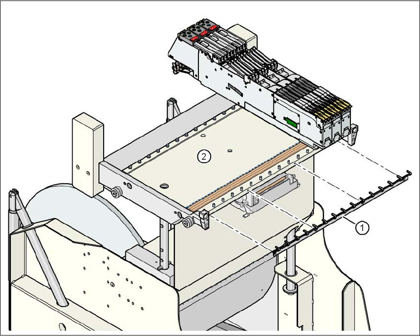
3.12.9 Feeder module fixing, SIPLACE HF component trolley
Item no. 00119623-xxFeeder module fixing, SIPLACE HF/X/D3
The feeder module fixing is an additional mechanical locking device. It prevents the feeder mod-
ules accidentally moving on the component table and thus prevents the risk of collision with the
placement head.
The feeder module fixing is fixed to the front panel of the component table using screws. The claws
fix the feeder module feet. One feeder module fixing is needed for each component trolley.
3
Fig. 3.12 - 8 Feeder module fixing, SIPLACE HF component trolleys
3
(1) Feeder module fixing
(2) Component table
User Manual SIPLACE X-Series 3 Technical data for the machine
From software version SR.605.xx 07/2008 EN Edition 3.12 SIPLACE HF component trolley
235
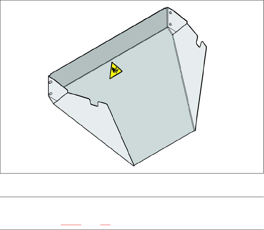
3.12.10 Used tape chute, SIPLACE HF
3
Fig. 3.12 - 9 Used tape chute for SIPLACE HF
PLEASE NOTE 3
The SIPLACE HF used tape chute can only be installed on the SIPLACE HF component trolley
docking unit (see Fig. 5.11 - 6, page 364.
3 Technical data for the machine User Manual SIPLACE X-Series
3.12 SIPLACE HF component trolley From software version SR.605.xx 07/2008 EN Edition
236
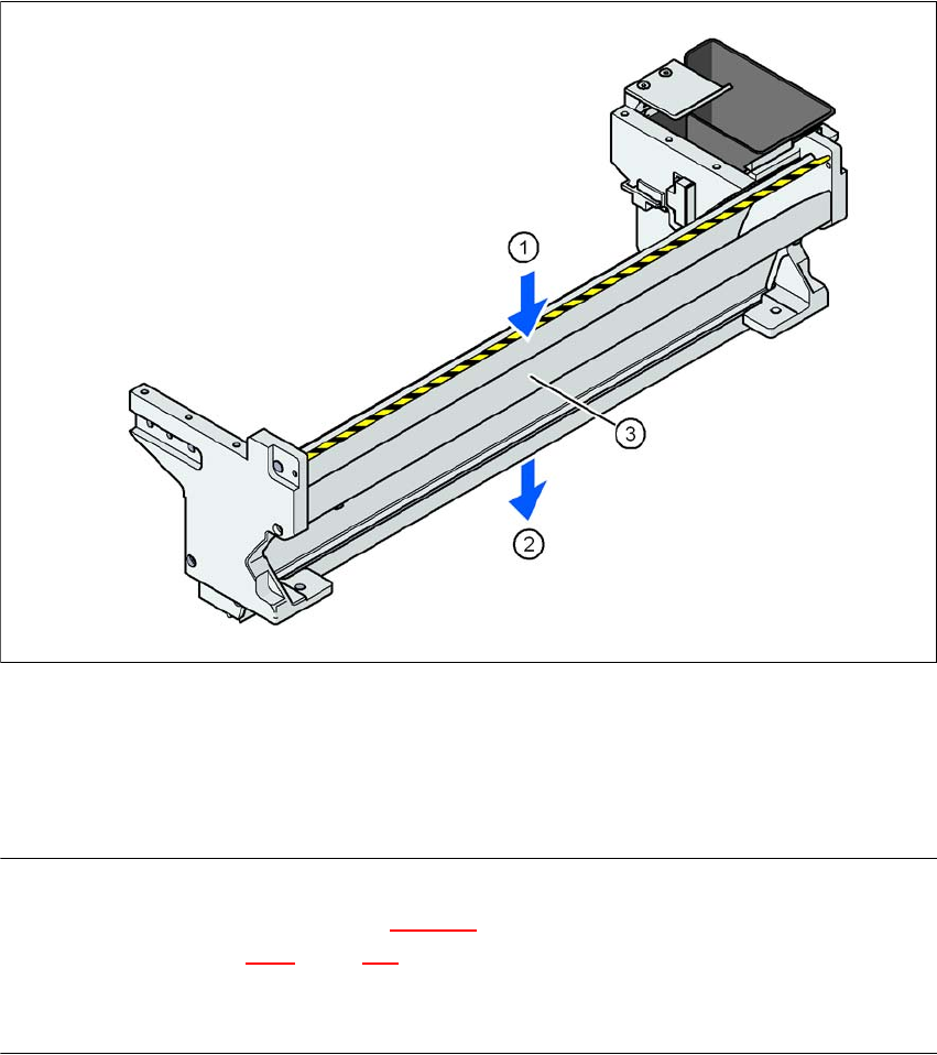
3.12.11 Used tape channel on the SIPLACE HF component trolley docking unit
In the standard version, the used tape channel can guide component tapes with a maximum
pocket height of 17 mm to the pneumatic tape cutter.
3
Fig. 3.12 - 10 Used tape channel on the SIPLACE HF component trolley docking unit
(1) Inlet slot for the used tapes
(2) Outlet slot for the used tape above the pneumatic tape cutter
(3) Dividing plate for tapes < 17 mm (can be removed for tapes > 17 mm)
PLEASE NOTE
– The separating plate (item 3 in Fig. 3.12 - 10
) can be removed for tape pockets higher than
17 mm (see Section 4.6.2
, page 316).
→ Do not position feeder modules with shallow pockets immediately beside feeder modules with
deep pockets. The used tapes could overlap and build up.