00195722-0102_UM_X-Serie_SR605_EN.pdf - 第131页
User Manual SIPLACE X-Series 3 Technical data for the machine From software version SR.605.xx 07/2008 EN Edition 3.5 Placement head 131 3.5.3.1 Description The 6-nozzle Co llect & Place head als o works on th e Colle…
3 Technical data for the machine User Manual SIPLACE X-Series
3.5 Placement head From software version SR.605.xx 07/2008 EN Edition
130
3
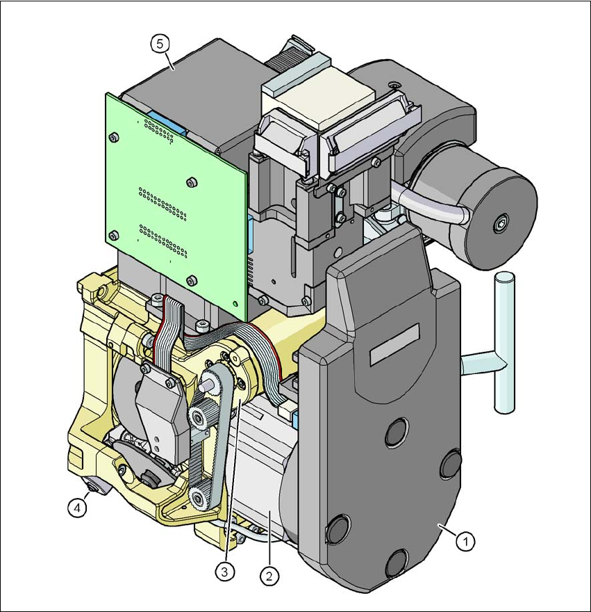
Fig. 3.5 - 6 6-segment Collect&Place head - Function groups, part 2
3
(1) Intermediate distributor board, beneath the cover
(2) Star drive - DR motor
(3) Z axis motor
(4) Valve adjustment drive
(5) C&P component camera, type 29, 27 x 27, digital
User Manual SIPLACE X-Series 3 Technical data for the machine
From software version SR.605.xx 07/2008 EN Edition 3.5 Placement head
131
3.5.3.1 Description
The 6-nozzle Collect & Place head also works on the Collect & Place principle. The high-resolution
digital component camera allows the 6-segment Collect&Place head to place components with an
edge length of up to 27 mm accurately and very quickly. It is therefore ideal for use with products
containing a large proportion of ICs. A considerable increase in output can be achieved even in
the main application range from PLCC 44 to QFP 208.
3.5.3.2 Technical data
3
6-segment Collect&Place head with high-resolution compo-
nent camera, type 29, 27 x 27, digital
(see Section 3.8.5
, page 159)
Range of components
a
0201 to 27 x 27 mm²
Component specification
max. height
min. lead pitch
min. lead width
min. ball pitch
min. ball diameter
min. dimensions
max. dimensions
max. weight
8.5 mm
0.3 mm
0.15 mm
0.25 mm for components< 18 x 18 mm²
0.35 mm for components ≥18 x 18 mm²
0.14 mm for components < 18 x 18 mm²
0.2 mm for components ≥18 x 18 mm²
0.6 x 0.3 mm²
27 x 27 mm²
5 g

3 Technical data for the machine User Manual SIPLACE X-Series
3.5 Placement head From software version SR.605.xx 07/2008 EN Edition
132
Programmed power stage
1
2
3
4
5
Programmed set-down force [N]
2.4 ± 0.5
2.4 ± 0.5
3 + 1
4 + 1
5 + 1
Nozzle types 8 xx, 9 xx
X/Y accuracy
b
± 45 μm/3σ, ± 60 μm/4σ
Angular accuracy ± 0.2°/3σ, ± 0.3°/4σ
Component range 99.5%
CO camera type 29
Illumination level 5
Possible illumination level settings
256
5
a) Please note that the component range that can be placed is also affected by the pad geometry, the cus-
tomer-specific standards and the packaging tolerances.
b) The accuracy value was measured using the vendor-neutral IPC standard.