00195722-0102_UM_X-Serie_SR605_EN.pdf - 第378页
6 Station extensions User Manual SIPLACE X-Series 6.1 Nozzle changer From software version SR.605.xx 07/2008 EN Edition 378 6.1.1.10 "Row 2" nozzle changer for the 20-segment Collec t&Place head Item no. 00…
User Manual SIPLACE X-Series 6 Station extensions
From software version SR.605.xx 07/2008 EN Edition 6.1 Nozzle changer
377
PLEASE NOTE 6
– Move the locking plate into the "Magazine locked" position.
– Before inserting, align the magazine so that the centering pins (item 2 and 6 in Fig. 6.1 - 6
,
page 376) slide into the centering holes and slot (item 6 in Fig. 6.1 - 6, page 376).
→ Place the magazine on the snap fastener balls (item 5 in Fig. 6.1 - 6
, page 376).
→ Press the magazine down evenly so that the snap fastener balls engage in all the snap fasten-
ers at the same time.
6.1.1.9 Position detection
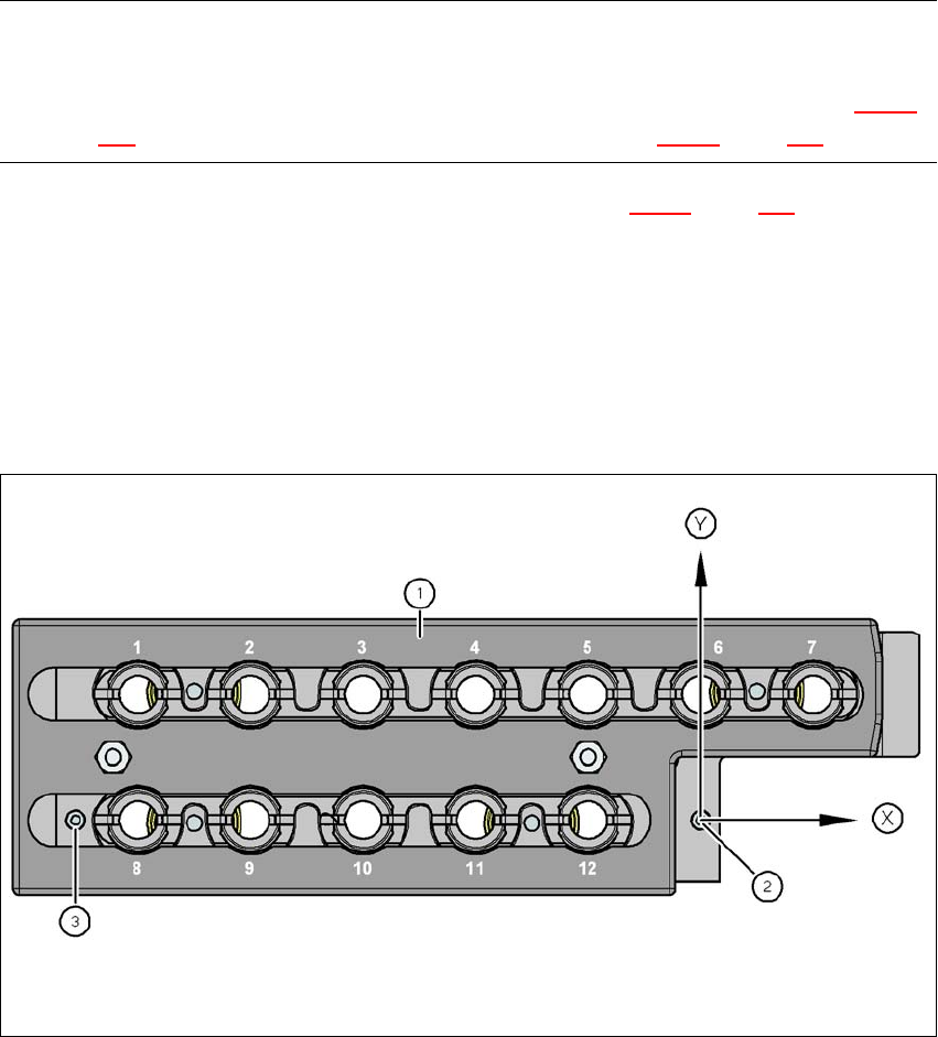
Each magazine of the nozzle changer has two fiducials: one for determining the position and one
for determining the angular position.
6
Fig. 6.1 - 7 Nozzle magazine - holder numbering, fiducials for determining the position and angular position
(1) Locking plate in the "Magazine open" position
(2) Fiducial for determining the position
(3) Fiducial for determining the angular position
6 Station extensions User Manual SIPLACE X-Series
6.1 Nozzle changer From software version SR.605.xx 07/2008 EN Edition
378
6.1.1.10 "Row 2" nozzle changer for the 20-segment Collect&Place head
Item no. 00119716-xx Nozzle changer 2, X-series, C&P20A
The "row 2" nozzle changer may be installed at the following locations:
X4 placement machine:Locations 1, 2, 3 and 4 (see Fig. 6.1 - 2
, page 371)
X3 placement machine:Locations 1, 3 and 4 (see Fig. 6.1 - 3
, page 372)
X2 placement machine:Locations 1 and 3 (see Fig. 6.1 - 4
, page 373)
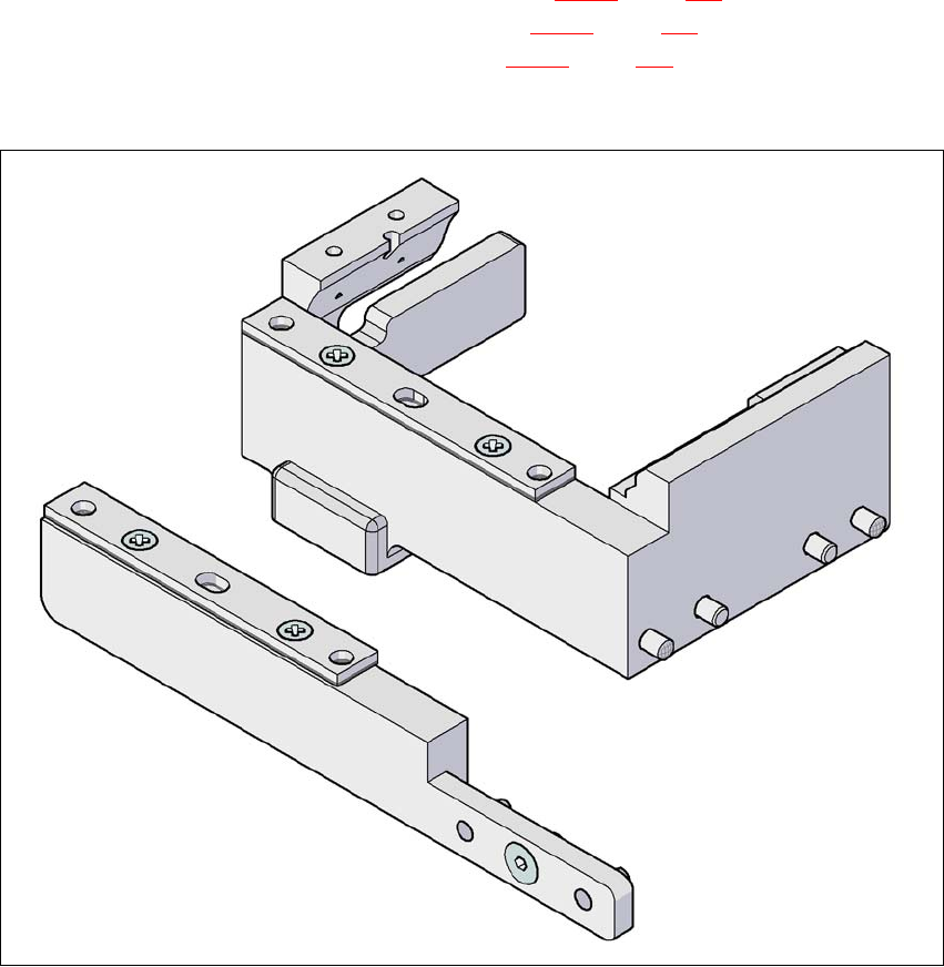
The retrofit package contains an assembly kit.
6
Fig. 6.1 - 8 Assembly kit for the "row 2" nozzle changer
6
6
User Manual SIPLACE X-Series 6 Station extensions
From software version SR.605.xx 07/2008 EN Edition 6.1 Nozzle changer
379
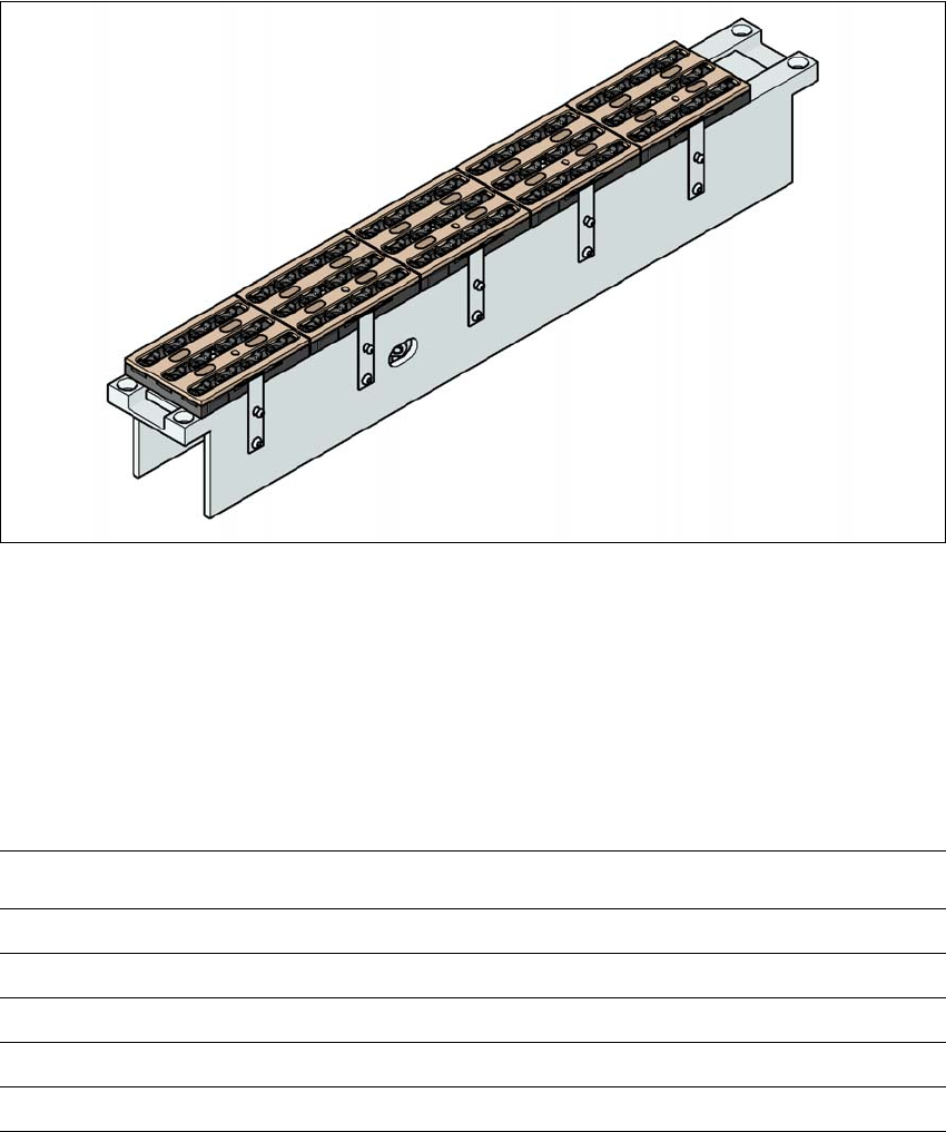
6.1.2 Nozzle changer for the 12-segment Collect&Place head
Item no. 00119661-xx Nozzle changer, HF/X/D3, 12-segment C&P head
6
Fig. 6.1 - 9 Nozzle changer for the 12-segment Collect&Place head
6.1.2.1 Description
This nozzle changer can hold up to 5 magazines, each with 12 nozzle holders. The magazines
are seated on a common support. They are centered using two parallel pins and fixed in place with
clips.
6.1.2.2 Technical data
6
Nozzle changer for the 12-nozzle Collect&Place head
Dimensions (length x width x height) 449 x 62.7 x 77.7 mm³
Number of nozzle holders 60
Nozzle types 9 xx
Nozzle changeover time approx. 2 sec. per nozzle
Compressed air connection 0.48 MPa (4.8 bar)