00195722-0102_UM_X-Serie_SR605_EN.pdf - 第67页
User Manual SIPLACE X-Series 2 Operational safety From software version SR.605.xx 07/2008 EN Edition 2.5 Safety instructions for operating the machine 67 2.5.4 Safety instructions for manuall y moving the Z axis at the T…
2 Operational safety User Manual SIPLACE X-Series
2.5 Safety instructions for operating the machine From software version SR.605.xx 07/2008 EN Edition
66
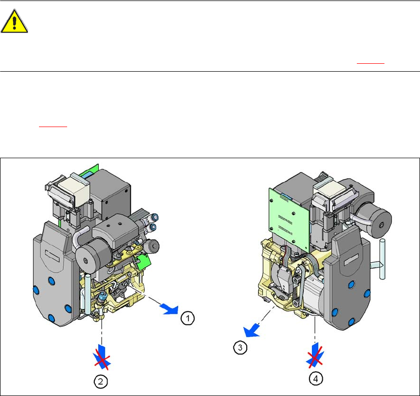
2.5.3 Safety instructions for removing nozzles from Collect&Place heads
CAUTION
RISK OF INJURY TO FINGERS BY SHARP NOZZLES 2
Do not remove the nozzles in the pick-up/placement position (item 2 and 4 in Fig. 2.5 - 2).
The procedure for removing nozzles manually from the sleeve is as follows:
→ Pace the sleeve from which the nozzle is to be removed to the removal point (item 1 and 3 in
Fig. 2.5 - 2
).
→ Remove the nozzle from the sleeve here.
2
Fig. 2.5 - 2 Position of the sleeve during a manual nozzle change
(1) Removal position for sleeves and nozzles, C&P12
(2) Pick-up and placement position, C&P12
(3) Removal position for sleeves and nozzles, C&P6
(4) Pick-up and placement position, C&P6
User Manual SIPLACE X-Series 2 Operational safety
From software version SR.605.xx 07/2008 EN Edition 2.5 Safety instructions for operating the machine
67
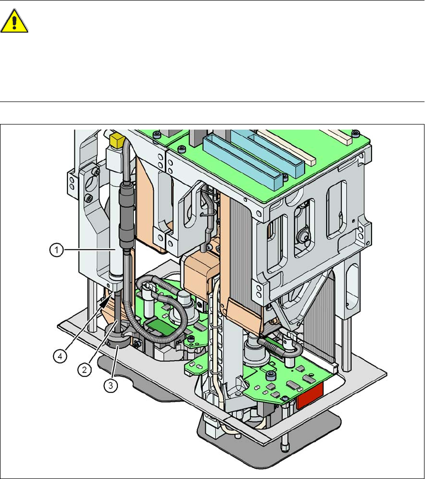
2.5.4 Safety instructions for manually moving the Z axis at the TwinHead
CAUTION
RISK OF CRUSHING AT THE TWINHEAD 2
NEVER move the Z axis down with your hand at the buffer of the return unit. The powerful spring
force of the cylinder creates a risk of injury to your fingers due to the buffer springing back. The
same applies inside the TwinHead when the piston rod springs back into its starting position.
Fig. 2.5 - 3 Risk of crushing from the return unit on the TwinHead
(1) Return unit, compressed air cylinder
(2) Piston rod
(3) Buffer of the return unit
(4) Risk of crushing to fingers
2 Operational safety User Manual SIPLACE X-Series
2.5 Safety instructions for operating the machine From software version SR.605.xx 07/2008 EN Edition
68
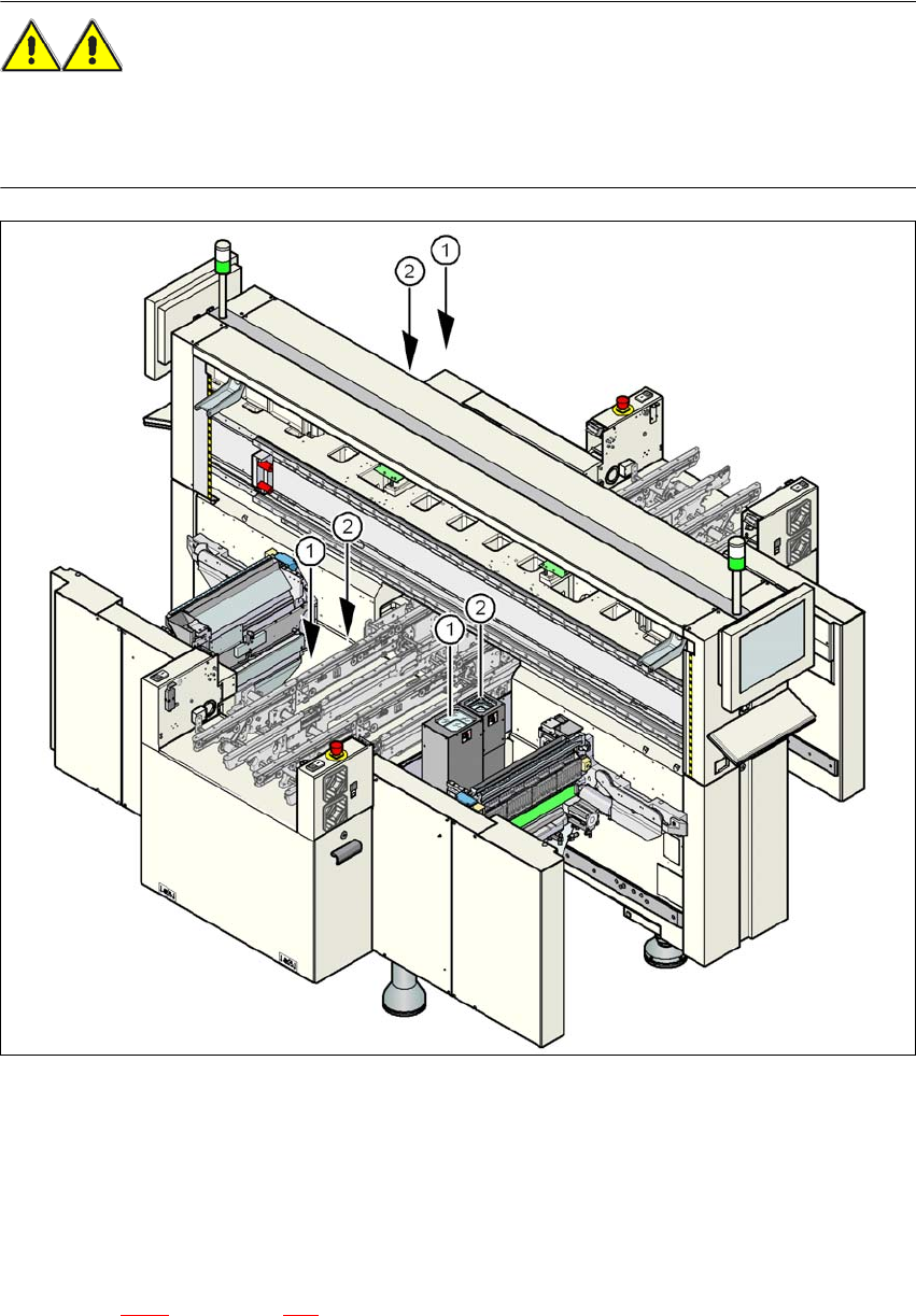
2.5.5 Safety instructions for the TwinHead component cameras during
a placement head change
WARNING 2
When the placement head is changed from the TwinHead to the Collect&Place head, the Twin-
Head's component cameras (stationary, P&P, type 33, 55 x 45, and type 25, 16 x 16) must be
removed, otherwise the Collect&Place head will collide with the camera housings.
2
Fig. 2.5 - 4 Safety instructions for the TwinHead vision modules during a placement head change
(1) Assembly position for the component camera (stationary, P&P, type 33, 55 x 45) with refer-
ence to the X3
(2) Assembly position for the component camera (stationary, P&P, type 25, 16 x 16) with refer-
ence to the X3
The assembly positions for all placement machines from the SIPLACE X-series are shown in
Section 3.8.2
, from page 154. 2