00195722-0102_UM_X-Serie_SR605_EN.pdf - 第22页
1 Introduction User Manual SIPLACE X-Series 1.1 Description of the machine From software version SR.605.xx 07/2008 EN Edition 22 1.1.3 SIPLACE X2 The X2 placement machine has one gantry per placement area. The following …

User Manual SIPLACE X-Series 1 Introduction
From software version SR.605.xx 07/2008 EN Edition 1.1 Description of the machine
21
1.1.1 SIPLACE X4
The X4 placement machine is equipped with four gantries, two gantries for each placement area
(PA). All the gantry axes are driven by linear motors. The gantry axes can be positioned quickly
and accurately in the X and Y directions. The gantry arms are lightweight constructions made from
a highly rigid carbon fiber composite material. There is a placement head on each gantry. The fol-
lowing placement head configurations are possible:
a) Placement area 1
b) Placement area 2
The performance data can be found in Section 3.1 on page 103.
1.1.2 SIPLACE X3
The X3 placement machine has 3 gantries, 2 of which are in placement area 1 and one is in place-
ment area 2. This allows the following placement head configurations:
a) Placement area 1
b) Placement area 2
The performance data can be found in Section 3.1 on page 103.
1
Placement heads Placement heads PA1
a
PA2
b
C&P20A /
C&P20A
C&P12/
C&P12
C&P12/
C&P6
C&P12/TH C&P6/
C&P6
C&P6/TH TH/TH
C&P20A/C&P20A yes no no no no no no
C&P12 / C&P12 yes yes no no no no no
C&P12 / C&P6 yes yes yes no no no no
C&P6 / C&P6 yes yes yes no yes no no
C&P12/TH yes yes yes yes no no no
C&P6/TH yes yes yes yes yes yes no
TH/TH yes yes yes yes yes yes yes
1
Placement
heads
Placement heads PA1
a
PA2
b
C&P20A /
C&P20A
C&P12/
C&P12
C&P12/
C&P6
C&P12/TH C&P6/
C&P6
C&P6/TH TH/TH
C&P20A yesnononononono
C&P12 yes yes no no no no no
C&P6 yes yes yes no yes no no
TH yes yes yes yes yes yes yes

1 Introduction User Manual SIPLACE X-Series
1.1 Description of the machine From software version SR.605.xx 07/2008 EN Edition
22
1.1.3 SIPLACE X2
The X2 placement machine has one gantry per placement area. The following placement head
configurations are possible:
a) Placement area 1
b) Placement area 2
The performance data can be found in Section 3.1 on page 103.
1.1.4 The SIPLACE principle
The placement heads fetch the components from the fixed feeder modules on the component trol-
ley or from the trays in the matrix tray changer, and place the PCBs, which are also stationary. The
placement machines from the X-series have two placement areas:
– on the single conveyor, one or two PCBs can be placed concurrently.
– on the dual conveyor, up to four PCBs can be placed concurrently.
The principle of the "stationary component supply" and "stationary PCB", which has proved most
suitable for all SIPLACE placement machines, has a number of significant advantages:
– There are no downtimes for topping up components or splicing tapes.
– The vibration-free component feeder means that even the smallest components (e.g. 01005)
are picked up reliably.
– The PCB, which does not move during the placement process, prevents the components slip-
ping.
– The combination of placement heads with nozzle changers always guarantees an optimum
nozzle configuration for every placement process, thus minimizing traversing paths and opti-
mizing the placement sequence.
High flexibility, cost-effectiveness and set-up reliability combine to ensure that the SIPLACE X-se-
ries provides high productivity. Minimum down times increase utilization and thus help to increase
productivity.
1
Placement
heads
Placement heads PA1
a
PA2
b
C&P20A C&P12 C&P6 TH
C&P20A yes no no no
C&P12 yes yes no no
C&P6 yes yes yes no
TH yes yes yes yes
User Manual SIPLACE X-Series 1 Introduction
From software version SR.605.xx 07/2008 EN Edition 1.1 Description of the machine
23
1
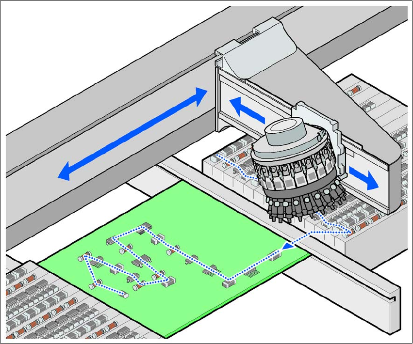
Fig. 1.1 - 1 Placement principle using the Collect&Place method
1
1
1
1.1.5 New options and performance features
The following new options are available to extend the machine's functionality:
– SIPLACE XPL
The "SIPLACE X-series Productivity Lane" option in the middle of the dual PCB conveyor al-
lows PCBs to be overtaken in the placement machine. As with the productivity lift, the place-
ment machine is operated in parallel. This third conveyor track can be viewed from above,
and even works with the protective cover open. This allows the path that the PCB takes
through the machine to be followed for checking purposes.
– SIPLACE XPS
SIPLACE X-series productivity shuttles on the input/output side of the machine or line distrib-
ute the PCBs to be processed to the required track of the dual PCB conveyor or to the
SIPLACE XPL.