00195722-0102_UM_X-Serie_SR605_EN.pdf - 第351页
User Manual SIPLACE X-Series 5 Tasks for the operating personnel From software version SR.605.xx 07/2008 EN Edition 5.7 Observe LCD and status displays on the X feeder module 351 5.7 Observe LCD and st atus displays on t…
5 Tasks for the operating personnel User Manual SIPLACE X-Series
5.6 Setting up the feeder modules From software version SR.605.xx 07/2008 EN Edition
350
5
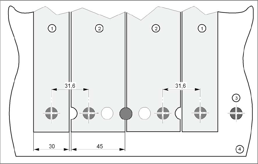
Fig. 5.6 - 10 Inserting 30 or 45 mm wide S feeder modules on the component table
(1) Feeder module, 30 mm wide
(2) Feeder module, 45 mm wide
(3) Centering ball
(4) Component table
5.6.6 Setting up the X feeder module
Setting up the X feeder modules is described in the job guide.
User Manual SIPLACE X-Series 5 Tasks for the operating personnel
From software version SR.605.xx 07/2008 EN Edition 5.7 Observe LCD and status displays on the X feeder module
351
5.7 Observe LCD and status displays on the X feeder
module
The X feeder modules have a multicolor status display (Pos. 6 in Fig. 5.7 - 1) for signaling the op-
erating statuses and an LCD display (item 1 in Fig. 5.7 - 1
) to display the texts.
5
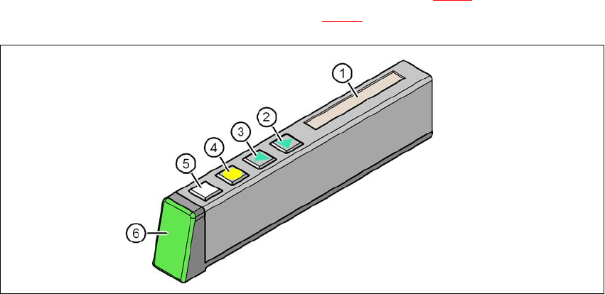
Fig. 5.7 - 1 Buttons, LCD and status displays on the X feeder module
(1) LCD display
(2) FORWARD button
(3) BACK button
(4) FOIL button
(5) SET button
(6) Status display, multicolor
5.7.1 Status display
–Green:
The feeder module is on standby and is contained in the current set-up.
– Orange:
A warning is being signalized. The text of the warning appears on the LCD display.
–Red:
A malfunction has occurred. The error message is output on the LCD display.
– OFF:
The feeder module is not contained in the current set-up.

5 Tasks for the operating personnel User Manual SIPLACE X-Series
5.7 Observe LCD and status displays on the X feeder module From software version SR.605.xx 07/2008 EN Edition
352
PLEASE NOTE 5
The machine controller switches off the status display of any feeder modules not included in the
set-up. The "LED off" status only occurs when the programming system has preset a job on the
line. This takes some of the work away from the operator since he only has to watch those feeder
modules that are contained in the set-up.
For the actual set-up process - no set-up information at the station, no job sent from SIPLACE
Pro to the station/line - the LED on each feeder module is activated after the set-up has been
made. The operator is thus informed whether everything is OK.
5.7.2 LCD display
The following tables containing the wording of the LCD display, the color and the mode of the sta-
tus display, its meaning and troubleshooting measures.
5.7.2.1 Warnings and remedies
5
5
5.7.2.2 Error messages and remedies
5
Text on the
LCD display
Status
display
Meaning Trouble-shooting
Remove Foil
(Remove the foil)
Orange The selected function is not
permitted when the cover foil
is tensioned (foil rocker is
pressed down).
If you wish to carry out that function, remove
the foil from the pair of gear wheels and cut
it off to relieve the pressure on the foil rocker.
Text on the
LCD display
Status
display
Meaning Trouble-shooting
none Red,
flashing
Feeder module software not
jumping to the application
Reload the application software
Load feeder module software
Handle --->>
(Handle --->>)
Red Feeder module was sig-
naled, but removal handle is
not yet pushed in
Push in the removal handle
Low Voltage
(Low voltage)
Orange 24V supply voltage did not
rise above the switch-on
threshold after switching on
Check the power supply