00195722-0102_UM_X-Serie_SR605_EN.pdf - 第280页
4 Setting up and commissioning User Manual SIPLACE X-Series 4.3 Setting up the placement machine From software version SR.605.xx 07/2008 EN Edition 280 4.3.9 Fitting the input conveyor 4.3.9.1 T ools – Allen keys, DIN 91…

User Manual SIPLACE X-Series 4 Setting up and commissioning
From software version SR.605.xx 07/2008 EN Edition 4.3 Setting up the placement machine
279
→ Check the switch settings for S1
1: ON
2: Not used
4.3.8.7 Fitting the axis unit
→ Carefully lift the axis unit onto the rail in the extension kit.
→ Make sure that you do not squash any cables.
→ Push the axis unit into the extension kit as far as the stop.
→ Secure the axis unit with the fillister head screw.
→ Insert the cover.
→ Fix the grounding cable to the doors (item 2 in Fig. 4.3 - 8
, page 267),
as shown in Fig. 4.3 - 9
on page 270.
→ Lock the doors.
4.3.8.8 Fitting the side plates
→ Fix the grounding cable to each side plate (item 6 in Fig. 4.3 - 8, page 267), as shown in Fig.
4.3 - 9
page 270.
→ Fix the side plate to the machine frame with 6 fillister head screws.
PLEASE NOTE 4
If you have dismantled the output conveyor, continue from Section 4.3.9
" Fitting the input con-
veyor" on page 280.
Once the input conveyor is fitted, then continue the assembly work from Section 4.3.13
"Fitting
the indicator lamp" on page 293.
X09_3sq X09_3sq 03050896 Snap connector into place
X10_3sq X10_3sq 03050895 Snap connector into place
X11_3sq X11_3sq 03050906 Snap connector into place
X12_3sq X12_3sq 03050905 Snap connector into place
X30_1sq X30_1sq 03010054 Screw tightly
X30_2sq X30_2sq 03010054 Screw tightly
Axis unit, plugs Connecting cable PLEASE NOTE
Plug Cable
4 Setting up and commissioning User Manual SIPLACE X-Series
4.3 Setting up the placement machine From software version SR.605.xx 07/2008 EN Edition
280
4.3.9 Fitting the input conveyor
4.3.9.1 Tools
– Allen keys, DIN 911, set
– Phillips screwdriver, size 1
4.3.9.2 Assembly
4
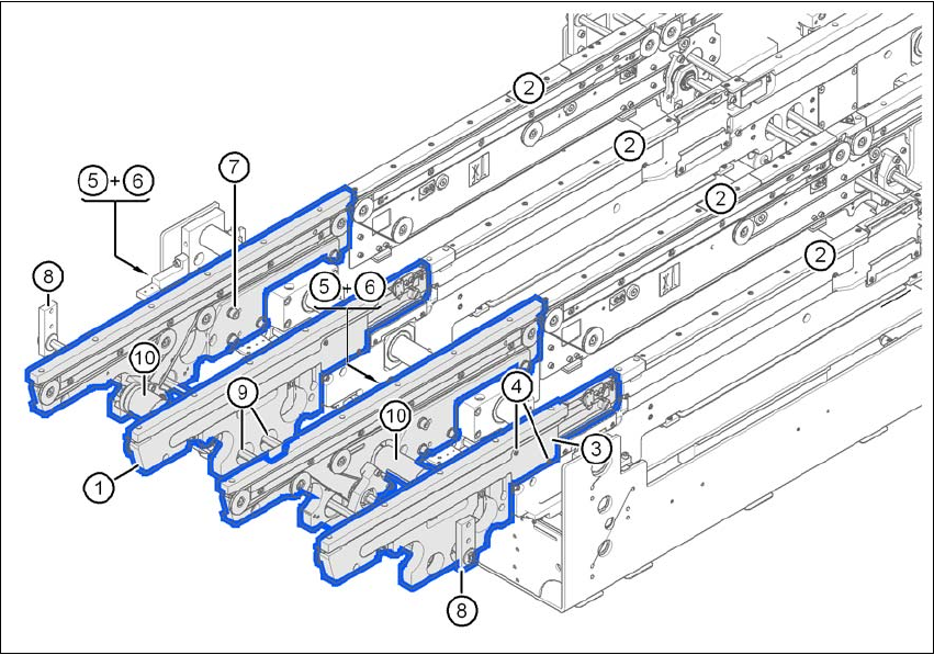
Fig. 4.3 - 14 Input conveyor - dual conveyor
(1) Rail, input conveyor
(2) rail, processing conveyor 1
(3) Cable cover 20 x 200
(4) Countersunk screw, ISO 7046, M3x6, 2x per cable cover
(5) Cable cover 20 x 310
(6) Fillister head screw DIN 912, M3x5, 1x per cable cover
(7) Fillister head screw DIN 912, M6x16, and washer, 4x per rail
(8) Guide for hexagonal shaft
(9) Hexagonal shaft (single conveyor: one, dual conveyor: two)
(10) drive unit

User Manual SIPLACE X-Series 4 Setting up and commissioning
From software version SR.605.xx 07/2008 EN Edition 4.3 Setting up the placement machine
281
→ Remove the cable covers (items 3 and 5 in Fig. 4.3 - 14, page 280) from the input conveyor
(item 1 in Fig. 4.3 - 14
, page 280).
→ Carefully place the rail (item 1 in Fig. 4.3 - 14
, page 280) against the rail on the processing
conveyor (item 2 in Fig. 4.3 - 14
, page 280).
CAUTION 4
Be careful not to cut through any of the light barrier or drive motor cables.
→ Fix each rail using 4 fillister head screws M6x16 and the associated washers (item 7 in Fig.
4.3 - 14
, page 280).
→ Connect the power cable to the light barriers and drive motors.
→ Fix the cable covers in place (item 3 and 5 in Fig. 4.3 - 14
, page 280).
→ Introduce the hexagonal shaft (item 9 in Fig. 4.3 - 14
, page 280) into the drive unit (item 10 in
Fig. 4.3 - 14
, page 280).
→ Make sure that the hexagonal shaft guide (item 8 in Fig. 4.3 - 14
, page 280) always points
towards the conveyor side wall to which the drive unit (item 10 in Fig. 4.3 - 14
, page 280) is
fixed.