00195722-0102_UM_X-Serie_SR605_EN.pdf - 第219页
User Manual SIPLACE X-Series 3 Technical data for the machine From software version SR.605.xx 07/2008 EN Edition 3.11 SIPLACE X-series component trolley 219 3.1 1.6 SIPLACE X-series component t able The front slider guid…
3 Technical data for the machine User Manual SIPLACE X-Series
3.11 SIPLACE X-series component trolley From software version SR.605.xx 07/2008 EN Edition
218
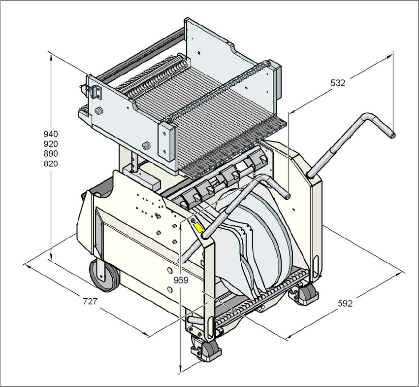
3.11.5 Dimensions of the component trolley, SIPLACE X-series
3
Fig. 3.11 - 5 Dimensions of the component trolley, SIPLACE X-series, all dimensions in millimeters
User Manual SIPLACE X-Series 3 Technical data for the machine
From software version SR.605.xx 07/2008 EN Edition 3.11 SIPLACE X-series component trolley
219
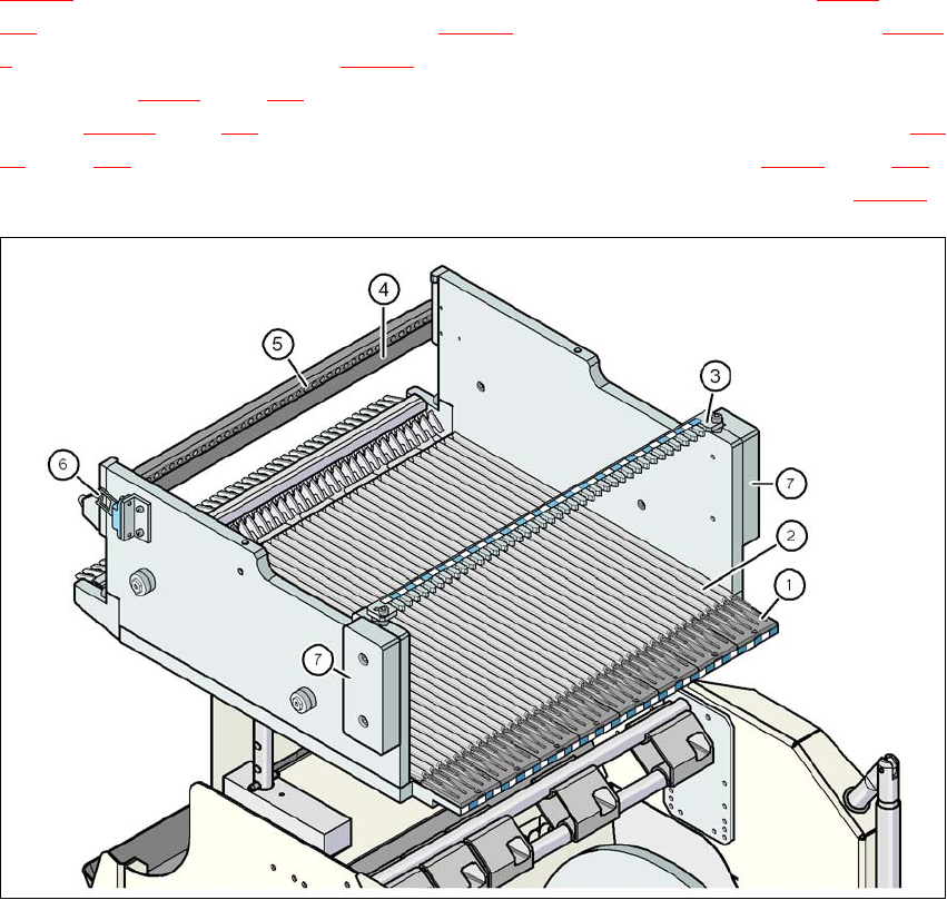
3.11.6 SIPLACE X-series component table
The front slider guides of the feeder modules are placed on the insertion aid (item 1 in Fig.
3.11 - 6
). As it is pushed in, the guides of the feeder module (item 12 and 13 in Fig. 3.9 - 2, page
167
) slide on the guide profile (item 2 in Fig. 3.11 - 6) as far as the stop bar (item 4 in Fig. 3.11 -
6). A centering hole (item 5 in Fig. 3.11 - 6, page ) on the stop bar holds the "front" centering pin
(item 4 in Fig. 3.9 - 1
, page 166) of the X feeder module. At the same time, the locking latch (item
1 in Fig. 3.11 - 7
, page 220) of the component table latches on the locking roller (item 1 in Fig. 3.9
- 1, page 166) of the feeder module. The "back" centering pin (item 12 in Fig. 3.9 - 1, page 166)
on the top of the feeder module is held by the recess in the centering bar (item 3 in Fig. 3.11 - 6
).
3
Fig. 3.11 - 6 Component table, SIPLACE X-series, back view
(1) Insertion aid
(2) Guide profile (Ω profile)
(3) Centering bar for holding the "back" centering pin for X feeder modules
(4) Stop bar
(5) Centering holes
(6) Contact for switching the safety switch of the EMERGENCY STOP circuit
(7) Hand guard
3 Technical data for the machine User Manual SIPLACE X-Series
3.11 SIPLACE X-series component trolley From software version SR.605.xx 07/2008 EN Edition
220
3
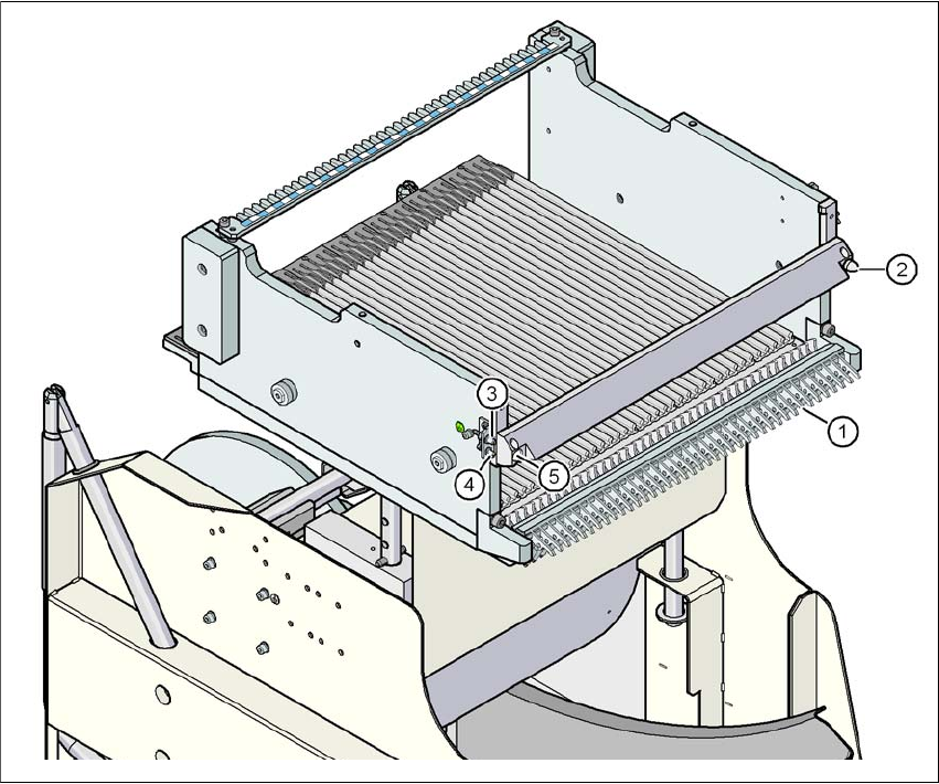
Fig. 3.11 - 7 Component table, SIPLACE X-series, front view
(1) Locking latches
(2) Centering pin on the component table
(3) Compressed air coupling
(4) Grounding pin
(5) Centering hole on the component table