00195722-0102_UM_X-Serie_SR605_EN.pdf - 第226页
3 Technical data for the machine User Manual SIPLACE X-Series 3.12 SIPLACE HF component trolley From software ver sion SR.605.xx 07/2008 EN Edition 226 CAUTION 3 The component trolleys from th e SIPLACE HF ma y only be d…
User Manual SIPLACE X-Series 3 Technical data for the machine
From software version SR.605.xx 07/2008 EN Edition 3.12 SIPLACE HF component trolley
225
3.12 SIPLACE HF component trolley
Item no. 00119622-xx Component trolley, SIPLACE HF/X-series/D3
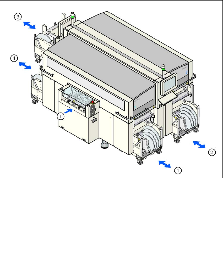
Up to four SIPLACE HF component trolleys can be docked into the machines from the SIPLACE
X-series. The locations are numbered as shown in the diagram below.
3
Fig. 3.12 - 1 Component trolley locations, SIPLACE HF
(1) Location 1
(2) Location 2
(3) Location 3
(4) Location 4
(T) PCB direction of travel
PLEASE NOTE 3
The SIPLACE HF component trolley cannot be used together with the 20-segment Collect&Place
head.
3 Technical data for the machine User Manual SIPLACE X-Series
3.12 SIPLACE HF component trolley From software version SR.605.xx 07/2008 EN Edition
226
CAUTION 3
The component trolleys from the SIPLACE HF may only be docked into locations at which the
component trolley docking unit for the SIPLACE HF is installed (Fig. 5.11 - 6, page 364).
The component trolleys are stand-alone modules that can be set up with feeders at an external
set-up area. This means that the production process only has to be interrupted briefly in order to
change the component trolley.
PLEASE NOTE:
At external set-up positions, you will need an external power supply for the component trolley
(see Section 3.12.6, page 231).
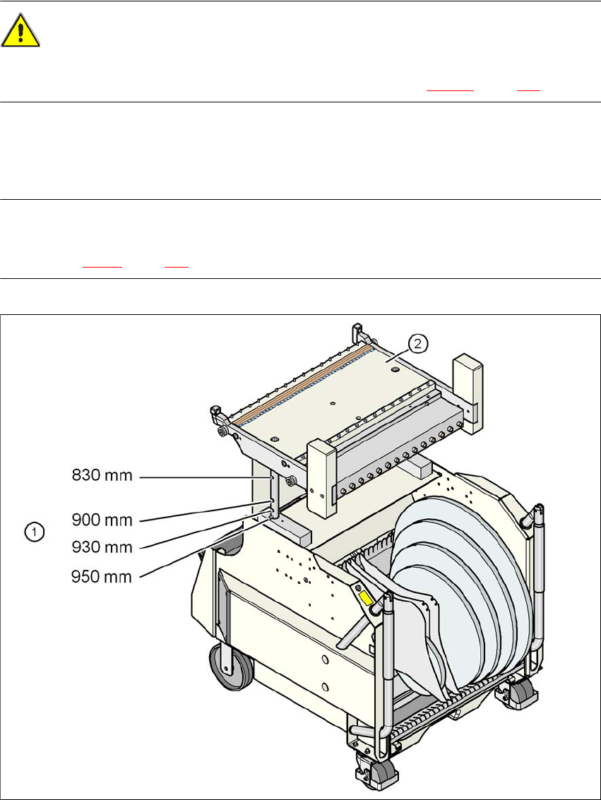
Fig. 3.12 - 2 SIPLACE HF component trolley with a PCB conveyor height of 950 mm
(1) Holes in the guide columns for the transport heights of 830 to 950 mm
(2) Component trolley table
User Manual SIPLACE X-Series 3 Technical data for the machine
From software version SR.605.xx 07/2008 EN Edition 3.12 SIPLACE HF component trolley
227
3.12.1 Structure
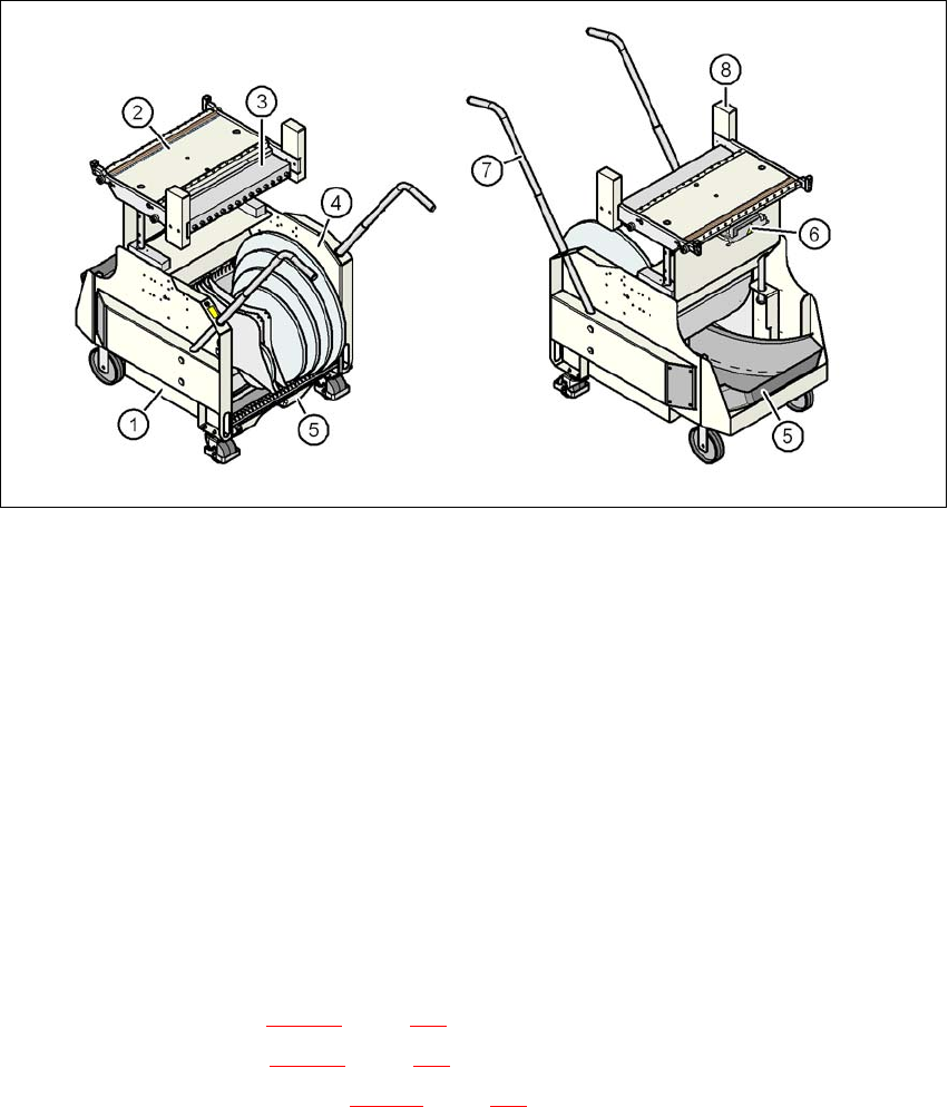
The component trolley essentially consists of the chassis, the component table for holding the
feeder modules, the communication unit, tape reel container and the waste tape container.
Fig. 3.12 - 3 SIPLACE HF component trolley - front and back view
(1) Chassis
(2) Component table
(3) Communication unit
(4) Tape reel container
(5) Waste tape container
(6) Interface for the main power supply, communication, the safety circuit and the compressed
air supply for the bulk case feeder module
(7) Handle
(8) Hand guard
3.12.2 Description
The chassis (item 1 in Fig. 3.12 - 3, page 227) runs smoothly and is easy to maneuver.
The handles (item 7 in Fig. 3.12 - 3
, page 227) can be folded up or down.
The component table (item 2 in Fig. 3.12 - 3
, page 227) has a capacity of up to 15 locations for 30
mm wide feeder modules. The feeder modules are mechanically centered on the table using cen-
tering pins and centering balls. The feeder modules are supplied with compressed air via a sepa-
rate compressed air bar.