00195722-0102_UM_X-Serie_SR605_EN.pdf - 第384页
6 Station extensions User Manual SIPLACE X-Series 6.1 Nozzle changer From software version SR.605.xx 07/2008 EN Edition 384 6.1.2.7 Notes on operation → When you fill a magazine with a certain nozzle type for the first t…
User Manual SIPLACE X-Series 6 Station extensions
From software version SR.605.xx 07/2008 EN Edition 6.1 Nozzle changer
383
6.1.2.6 Assembly
"Row 1" nozzle changers (see Figs. 6.1 - 10, 6.1 - 11 and 6.1 - 12 from page 380) are each fixed
to the component trolley docking unit. There is an additional assembly kit for the "row 2" nozzle
changer. This kit consists of the take-off device and the nozzle reject bin (see Section 6.1.2.10
,
page 387
).
6
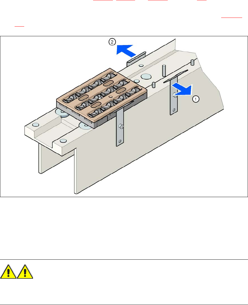
Fig. 6.1 - 13 Assembly position
(1) Spring hook pointing toward the operator
(2) Retaining clamp pointing toward the PCB conveyor
→ Align the nozzle changer so that the moving spring hooks always point toward the operator,
while the retaining clamps always point toward the PCB conveyor.
WARNING 6
– Only install the associated nozzle changer for each placement head. There is a risk of head
crashes with mixed configurations.

6 Station extensions User Manual SIPLACE X-Series
6.1 Nozzle changer From software version SR.605.xx 07/2008 EN Edition
384
6.1.2.7 Notes on operation
→ When you fill a magazine with a certain nozzle type for the first time, attach an adhesive label
to identify the type.
PLEASE NOTE 6
Fill the magazines off the machine and always replace complete magazines. 6
→ Open the locking plate and place the nozzles in the nozzle holders.
→ Close the locking plate so that the nozzles cannot drop out of the magazines.
CAUTION 6
Before you fill magazine, make sure that all the nozzles on the Collect&Place head have
been returned to their magazines. 6
→ Programming the nozzle changer is described in the SIPLACE Pro user manual.
PLEASE NOTE 6
→ Do not allow components to drop onto the magazines. If they do, they could jam the locking
plate.
→ Do not allow components to drop onto free feeder module locations. They will stick to the mag-
netic bar. Production may have to be interrupted if the feeder modules are not placed on the
component table correctly. You should therefore regularly clean the magazines and free loca-
tions.
User Manual SIPLACE X-Series 6 Station extensions
From software version SR.605.xx 07/2008 EN Edition 6.1 Nozzle changer
385
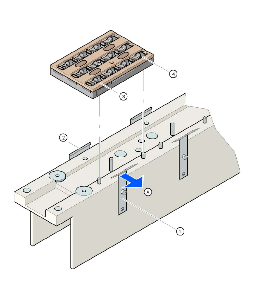
6.1.2.8 Changing the magazine
→ To remove the magazine, push the spring hook (item 1 in Fig. 6.1 - 14) away from the maga-
zine. Lift the magazine out of the carrier.
6
Fig. 6.1 - 14 Changing the magazine
(1) Spring hook
(2) Retaining clamp
(3) Centering hole
(4) Slot
(A) Push the spring hook away from the magazine