00195722-0102_UM_X-Serie_SR605_EN.pdf - 第361页
User Manual SIPLACE X-Series 5 Tasks for the operating personnel From software version SR.605.xx 07/2008 EN Edition 5.11 Docking the component trolley in or out 361 CAUTION 5 The component trolleys for the SIPLACE X-se r…
5 Tasks for the operating personnel User Manual SIPLACE X-Series
5.11 Docking the component trolley in or out From software version SR.605.xx 07/2008 EN Edition
360
→ Remember that a component trolley with the full complement of feeder modules can tip over
sideways or forward on gradients of 20° or more.
→ Make sure that the surface on which the trolley is moved has a significantly smaller gradient.
→ Be careful not to collide with obstacles. The trolley could tip forward if it is traveling fast
enough.
5.11.4 Docking the X-series component trolley
5
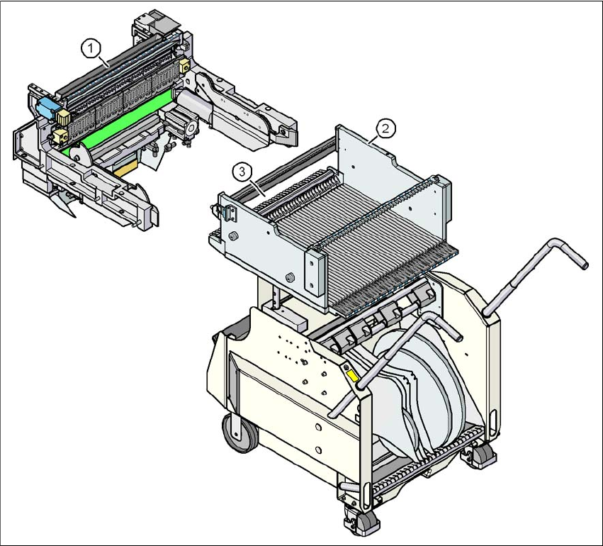
Fig. 5.11 - 3 Component trolley and component trolley docking unit, SIPLACE X-series
(1) Component trolley docking unit, SIPLACE X-series
(2) Component trolley, SIPLACE X-series
(3) Locking latches
User Manual SIPLACE X-Series 5 Tasks for the operating personnel
From software version SR.605.xx 07/2008 EN Edition 5.11 Docking the component trolley in or out
361
CAUTION 5
The component trolleys for the SIPLACE X-series (Fig. 5.11 - 3
, page 360) and SIPLACE HF
(Fig. 5.11 - 6
, page 364) have different docking units. Each component trolley must therefore only
be docked into the correct docking unit. Be careful when you push CO trolley for the SIPLACE X-
series into the machine and make sure that the locking latches (item 3 in Fig. 5.11 - 3
, page 360)
do not bump into obstacles.
PLEASE NOTE 5
Cut the component tapes off flush with the front end of the X feeder modules before you dock in
the component trolley.
CAUTION 5
Check that the placement head is outside the range of the component trolley.
→ Carefully push the component trolley into machine as far as the stop.
PLEASE NOTE 5
Close the protective covers since the component trolley can only be docked in if the covers are
closed.
→ Press the relevant button on the input or output side of the machine (item 1, 2, 3 or 4 in Fig.
5.11 - 1
, page 358), until the trolley is docked in fully.
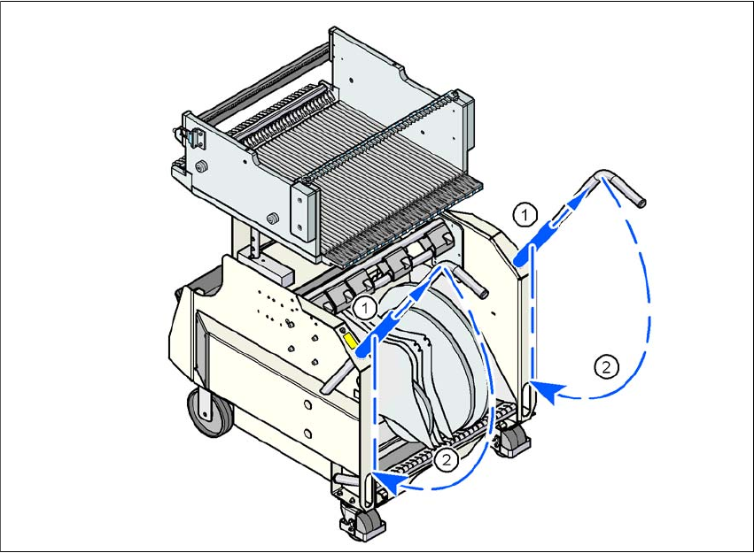
→ Push the sleeve (item 1 in Fig. 5.11 - 4
, page 362) up using both handles and swivel the han-
dle down (item 2 in Fig. 5.11 - 4
, page 362).
5 Tasks for the operating personnel User Manual SIPLACE X-Series
5.11 Docking the component trolley in or out From software version SR.605.xx 07/2008 EN Edition
362
5
Fig. 5.11 - 4 Component trolley X-series - swivel handles down
(1) Push sleeve up
(2) Fold handle down