Service Manual HS60.pdf - 第112页
4 G ant ri es HS- 6 0 S erv ice Ma nu al 4.9 R epl acin g the defl ection unit (00 33093 8-0 2) 03/ 2003 US Is sue 110 4.9 Repla cing the d eflection unit (0 0330938-02 ) 4.9.1 T o ols a nd equipm ent – Set of DIN 91 1 A…
HS-60 Service Manual 4 Gantries
03/2003 US Issue 4.8 Replacing the tensioning keys (00329478-01, 00329485-01)
109
4.8.4 Installing the tensioning keys
Installing the tensioning key, item 1 (synchronizing disk, short) 4
Æ Place the tensioning key on the ’short’ synchronizing disk (item 9 in Fig. 4.8 - 1).
Æ Use the M4 x 5 hexagon socket-head screw (item 8 in Fig. 4.8 - 1) to fix the tensioning key.
Installing the tensioning key, item 2 (synchronizing disk, long) 4
Æ Fit the spacer bolt with the Benzing U-clip (item 7 in Fig. 4.8 - 1) on the new tensioning key.
Æ Place the tensioning key on the ’long’ synchronizing disk (item 10 in Fig. 4.8 - 1).
Æ Use the size 8 Allen key to turn the synchronizing disk slightly until the hexagon socket-head
screw (item 3 in Fig. 4.8 - 1
) can be screwed in.
Æ Pre-tension the toothed belt by turning the hexagon socket-head screw clockwise.
4.8.5 Settings
Æ Push the head mount towards the X-axis motor as far as the stop on the elastomeric spring.
Æ Turn the hexagon socket-head screw to set the belt tension to 53 Hz + 1/-3 Hz.
CAUTION 4
Do not overstretch the toothed belt when adjusting the belt tension. 4
Æ Secure the hexagon socket-head screw (item 3 in Fig. 4.8 - 1) with the locknut (item 11 in Fig.
4.8 - 1
).

4 Gantries HS-60 Service Manual
4.9 Replacing the deflection unit (00330938-02) 03/2003 US Issue
110
4.9 Replacing the deflection unit (00330938-02)
4.9.1 Tools and equipment
– Set of DIN 911 Allen keys
– TSM belt tension measuring device, from item number 00326015-01
– "Measuring belt tensions" operating instructions
4.9.2 Parts
Deflection unit X, from item number 00330938-01 4
4.9.3 Removing the deflection unit
Æ Switch the placement system off and secure it to prevent switching on again as described in
Section 4.4
, page 100 onward.
Æ To slacken the toothed belt (item 9 in Fig. 4.9 - 1)
– loosen the locknut (item 11 in Fig. 4.9 - 1
) and
– turn the hexagon socket-head screw counter-clockwise (item 1 in Fig. 4.9 - 1
).
Æ Remove the M4 x 35 hexagon socket-head screw (item 1 in Fig. 4.9 - 1).
Æ Remove the tensioning key (item 2 in Fig. 4.9 - 1) from the synchronizing disk (item 3 in Fig.
4.9 - 1
).
Æ Pull the toothed belt (item 9 in Fig. 4.9 - 1) out through the opening in the tension jack (item 4
in Fig. 4.9 - 1
).
Æ Unthread the toothed belt from the deflection unit (item 8 in Fig. 4.9 - 1).
Æ Loosen the two M3 x 8 hexagon socket-head screws (item 6 in Fig. 4.9 - 1) and remove the y
brake ’external’ (item 5 in Fig. 4.9 - 1
).
Æ Loosen the two M6 x 10 hexagon socket-head screws (item 7 in Fig. 4.9 - 1) and remove the
deflection unit ’X’ (item 8 in Fig. 4.9 - 1
).
Æ Remove the elastomeric spring (item 10 in Fig. 4.9 - 1) from the deflection unit.
HS-60 Service Manual 4 Gantries
03/2003 US Issue 4.9 Replacing the deflection unit (00330938-02)
111
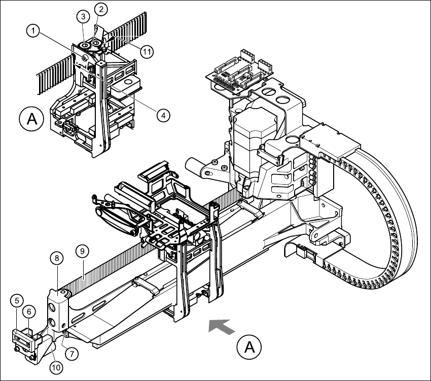
Fig. 4.9 - 1 Replacing the deflection unit
Key
(1) M4 x 35 hexagon socket-head screw (2) Tensioning key
(3) Synchronizing disk, long (4) Opening in tension jack for toothed belt
(5) Y-axis brake, external (6) 2 x M3 x 8 hexagon socket-head screws
(7) 2 x M6 x 10 hexagon socket-head screws (8) Deflection unit - X
(9) Synchroflex toothed belt (10) 25 x 10.5 x 50 elastomeric spring
(11) Locknut 4