Service Manual HS60.pdf - 第119页
HS -60 Se rvic e Manu al 4 Ga ntr ies 03/ 200 3 US I ssue 4. 10 R e plac in g the X -ax is t oot he d be lt ( 00 33 1076 - 02) 117 4.10.5 Se ttings Æ P ush the head moun t (item 1 in Fig. 4. 10 - 2 ) to wa rd s the X -a …
4 Gantries HS-60 Service Manual
4.10 Replacing the X-axis toothed belt (00331076-02) 03/2003 US Issue
116
4.10.4 Installing the X-axis toothed belt
Æ Place the toothed belt around the synchronizing disk of the X-axis motor unit (item 5 in Fig.
4.10 - 1
).
Æ Thread the toothed belt into the deflection unit (item 4 in Fig. 4.10 - 1).
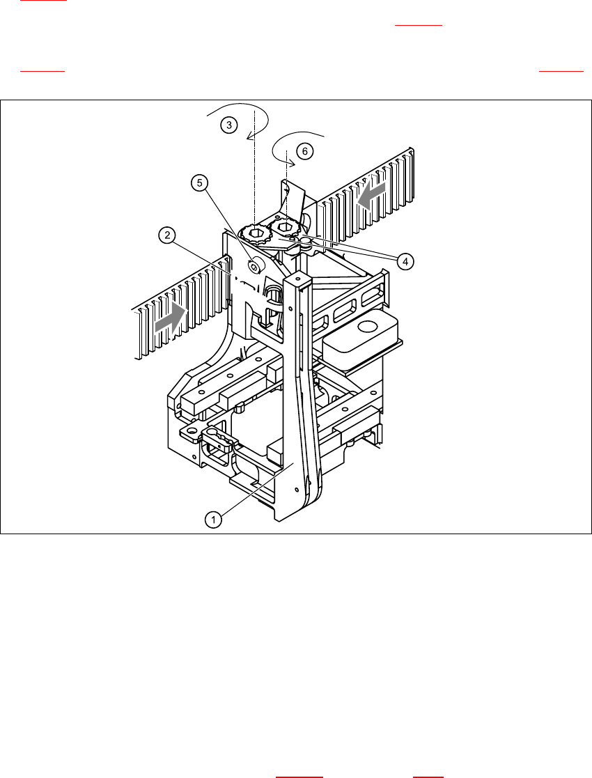
Æ Thread the two ends of the toothed belt into the openings on the tension jack (item 2 in Fig.
4.10 - 2
) until it runs approximately 270° around the synchronizing disks (item 3 in Fig. 4.10 - 2).
4
Fig. 4.10 - 2 Fixing the X-axis toothed belt to the tension jack
Key
(1) Head mount
(2) Tension jack
(3) Synchronizing disk, long
(4) Tensioning keys
(5) Hexagon socket-head screw for tensioning the toothed belt
(6) Synchronizing disk, short
Æ Fit the two tensioning keys (item 4 in Fig. 4.10 - 2) (see Section 4.8.4).
HS-60 Service Manual 4 Gantries
03/2003 US Issue 4.10 Replacing the X-axis toothed belt (00331076-02)
117
4.10.5 Settings
Æ Push the head mount (item 1 in Fig. 4.10 - 2) towards the X-axis motor unit as far as the stop
on the elastomeric spring.
Æ Turn the hexagon socket-head screw (item 5 in Fig. 4.10 - 2) to set the belt tension to
53 Hz + 1/-3 Hz.
CAUTION 4
Do not overstretch the toothed belt when adjusting the belt tension. 4
Æ Secure the hexagon socket-head screw (item 5 in Fig. 4.10 - 2) with the locknut.
4 Gantries HS-60 Service Manual
4.11 Replacing the X-axis motor unit (00333167-03) 03/2003 US Issue
118
4.11 Replacing the X-axis motor unit (00333167-03)
4.11.1 Tools and equipment
– Set of DIN 911 Allen keys
–Cable ties
– TSM belt tension measuring device, from item number 00326015-01
– "Measuring belt tensions" operating instructions
4.11.2 Parts
X-axis motor unit, from item number 00333167-03 4
4.11.3 Removing the X-axis motor unit
Æ Switch the placement system off and secure it to prevent switching on again as described in
Section 4.4
, page 100 onward.
DANGER POWERFUL MAGNETIC FIELD 4
Always follow the special safety instructions when working in the vicinity of powerful magnetic
fields (see Section 4.5, page 101). 4
Gantry 1 or 3 4
Æ Remove the black cover strip on the cross-beam above the gantry concerned:
– Remove the fan cable from the socket. The fan is fixed to the black cover strip.
– Remove the black cover strip (3 M6x8 hexagon socket-head screws).
Æ Cut the cable ties holding the X-axis motor cable.
Æ Remove the cable clamp for the flat ribbon cable (item 11 in Fig. 4.11 - 1)
Æ Unplug all the plugs from the X/Y distributor (item 5 in Fig. 4.11 - 1).
Æ Remove the X/Y distributor (item 5 in Fig. 4.11 - 1).
Æ Remove the board holder for the X/Y distributor (item 9 in Fig. 4.11 - 1).
Æ Remove the cable holder (item 10 in Fig. 4.11 - 1) for the trailing cable.