Service Manual HS60.pdf - 第179页
Se rv ice M a nu al HS-6 0 6 Mo du la r P CB con ve y or s yst em 03/ 2003 US Issu e 6 .10 Re plac ing the con veyor t ooth ed b elt (00364 847-0 1) 177 6.10.3 .1 Bel t tension HS 60 for conve yor track 1 (singl e and du…
6 Modular PCB conveyor system Service Manual HS-60
6.10 Replacing the conveyor toothed belt (00364847-01) 03/2003 US Issue
176
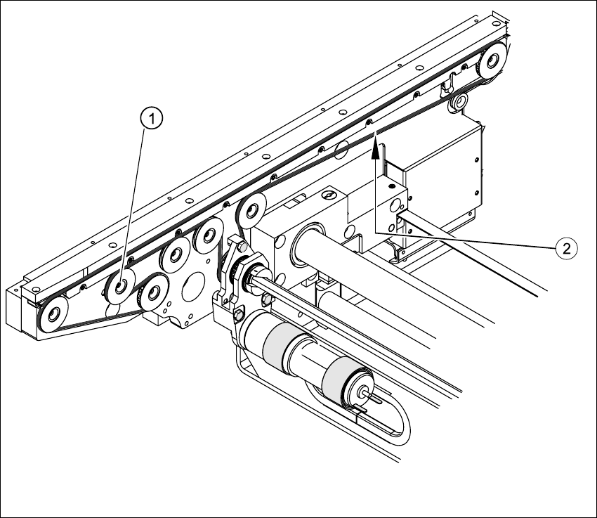
6.10.3 Adjusting the tension of the conveyor toothed belt
Fig. 6.10.8 Example for adjusting belt tension
Key
Æ The deflection pulleys, around which the conveyor toothed belt is run at approximately 180°,
are fastened at a slot. The tension of the conveyor toothed belt can be adjusted at this slot.
Æ Position the measuring point of the belt tension device at the strand center (i.e. the longest dis-
tance between the two deflection pulleys) of the conveyor toothed belt.
Æ Set the tension of the conveyor toothed belt according to the following values.
(1) Deflection pulley with slot (2) Measuring point of belt tension measuring
device (Strand center)
Service Manual HS-60 6 Modular PCB conveyor system
03/2003 US Issue 6.10 Replacing the conveyor toothed belt (00364847-01)
177
6.10.3.1 Belt tension HS 60 for conveyor track 1 (single and dual conveyor)
– Input conveyor: 170 Hz +/- 17 Hz
– Placement area 1: 70 Hz +/- 7 Hz
– Intermediate conveyor: 147 Hz +/- 15 Hz
– Placement area 2: 70 Hz +/- 7 Hz
– Output conveyor: 170 Hz +/- 17 Hz
6.10.3.2 Belt tension HS 60 for conveyor track 2 (dual conveyor)
– Input conveyor: 170 Hz +/- 17 Hz
– Placement area 1: 70 Hz +/- 7 Hz
– Intermediate conveyor:118 Hz +/- 12 Hz
– Placement area 2: 70 Hz +/- 7 Hz
– Output conveyor: 170 Hz +/- 17 Hz
6.10.3.3 Belt tension S 27 HM (single and dual conveyor)
Fixed conveyor side (DC motors)
– Input conveyor: 110 Hz +/- 5 Hz
– Placement area: 100 Hz +/- 5 Hz
– Output conveyor: 100 Hz +/- 5 Hz
6.10.3.4 Belt tension S 27 HM (single and dual conveyor)
Movable conveyor side
– Input conveyor: 95 Hz +/- 5 Hz
– Placement area: 110 Hz +/- 5 Hz
– Output conveyor: 150 Hz +/- 5 Hz

6 Modular PCB conveyor system Service Manual HS-60
6.11 Lifting table 03/2003 US Issue
178
6.11 Lifting table
DANGER
Please observe the safety instructions in Chapter 2.
6.11.1 Function
Depending on the model (single or dual conveyor), each placement area has one or two indepen-
dently functioning lifting tables in use. The lifting table is driven indirectly via a pneumatic cylinder,
with magnetic valve control. Different PCB thicknesses are automatically compensated. Move-
ment along the Z-axis is measured at four points on the lifting table plate. A position measuring
system determines the lifting path. The top position of the lifting table is recognized by the position
measuring system and a Piezo force transducer (see also Section 6.11.6
). The bottom position of
the lifting table is identified by the position measuring system and the end position proximity switch
on the pneumatic cylinder.
NOTE:
The standard space under the PCB is 40 mm. The previously used PCB supports are no longer
suitable.