Service Manual HS60.pdf - 第202页
6 M odul ar PCB co nveyo r sys tem S er vice Ma nual HS-6 0 6. 13 Widt h a dj us tme nt 0 3/2 00 3 US I ss ue 200 F ig. 6. 13. 22 O ver v iew o f wi dt h a dj us tme nt on th e S-27 H M Key CAUTION The bearing flange for…
Service Manual HS-60 6 Modular PCB conveyor system
03/2003 US Issue 6.13 Width adjustment
199
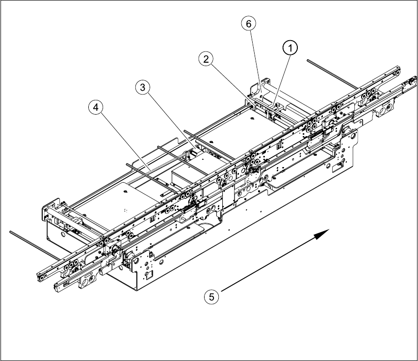
Fig. 6.13.21 Overview of width adjustment on the HS-60
Key
(1) Adjustment unit (4) Toothed belt for the width adjustment drive
(2) Synchronizing disk with spindle (5) Direction of travel
(3) Width adjustment stepping motor (6) Bearing flange
6 Modular PCB conveyor system Service Manual HS-60
6.13 Width adjustment 03/2003 US Issue
200
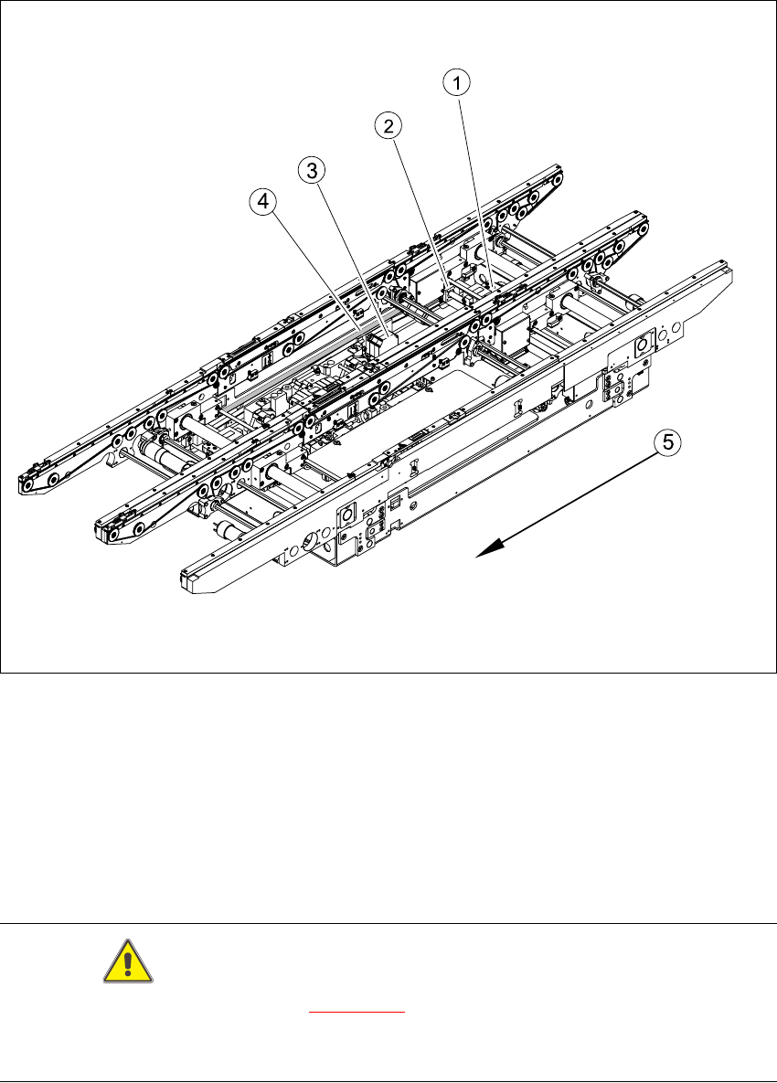
Fig. 6.13.22 Overview of width adjustment on the S-27 HM
Key
CAUTION
The bearing flange for the HS-60 (see Fig. 6.13.21
) and S-27 HM MUST NOT be loosened or ad-
justed. This would prevent the PCB conveyor from functioning and it would need to be completely
replaced.
(1) Adjustment unit (4) Toothed belt for the width adjustment drive
(2) Synchronizing disk with spindle (5) Direction of travel
(3) Width adjustment stepping motor
Service Manual HS-60 6 Modular PCB conveyor system
03/2003 US Issue 6.13 Width adjustment
201
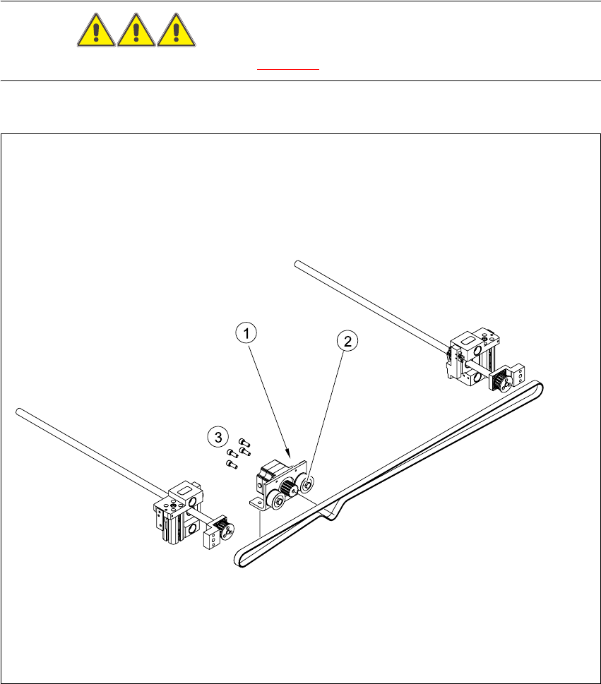
6.13.2 Replacing the stepping motor of the width adjustment system (00367174-02)
DANGER
Please observe the safety instructions in Chapter 2.
Fig. 6.13.23 Replacing the stepping motor of the width adjustment system
Key
(1) Loosening the eccentric axle on the deflec-
tion pulley
(3) Screws fastening the stepping motor
(2) Locknut on the eccentric axle