Service Manual HS60.pdf - 第247页
Se rv ic e Ma nu al HS- 6 0 6 Mo du la r P C B c onve y or s y st em 03/ 2 003 U S Iss ue 6 .17 Bl ock di agra ms for modu lar tra nspor t 245 Status Modified Date Name Standard Orig. Created for Created by Document stat…
6 Modular PCB conveyor system Service Manual HS-60
6.17 Block diagrams for modular transport 03/2003 US Issue
244
Status Modified Date Name Standard Orig. Created for Created by
Document status
Product status
Function status Date
Author
Checked
Sheet
Sh.
Weitergabe sowie
Vervielf
ä
ltigung diese
r Unterlage,Ver-
wertung u
nd Mitteilung ihres Inhalts nic
ht gestattet, soweit
nicht ausdr
ü
cklich zugestanden. Z
uwiderhandlungen
ver-
pflichten zu Schadene
rsatz. Alle Re
chte vorbehalten, ins
besondere
f
ü
r den Fall der Patenterteilun
g oder GM-Eintrag
ung
Proprietary date,
company confidentia
l. All rights reservd
.
Confie a titre de secret d
´
entreprise. Tous droits
reserves.
Comunicado como se
gredo empresarial. Res
ervados to
dos os direilos.
Confiado
como secre
te industrial. Nos reser
vamos todos los derechos.
Raabe
22.01.02
SIEMENS
DEMATIC
SD EA1 R&D
6
22.01.02
17.06.02
17.12.02
Raabe
Raabe
Raabe
02
02
01
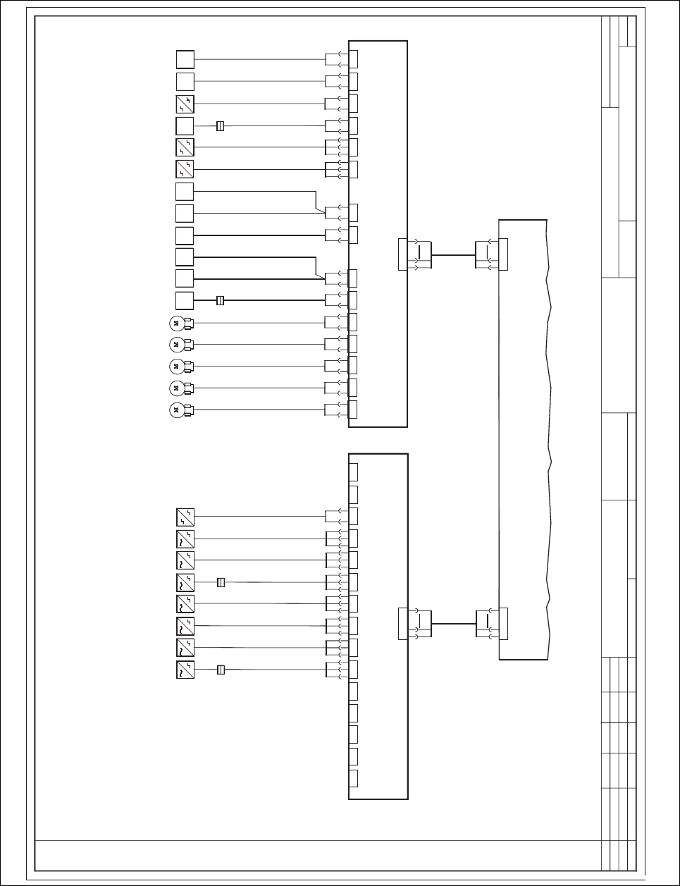
Wiring for PCB dual conveyor
00119462-010202LD3
Cable: belt motor, input belt
Cable: belt motor, placement sector 1
Cable: b
elt motor, intermediate belt
Cable: belt motor, output belt
Cable: belt motor, placement sector 2
Laser, transmitt
er f. placement sector 1
Laser, transmitter f. placement sector 2
00363092-xx
00363094-xx
00362345-xx
Piezo sensor f. PCB clamping
Placement sector 2
Piezo sensor f. PCB clamping
Placement sector 1
Limit switch f. width adjustment
Light barrier f. PCB detection, transmitter
Input belt 00371366-xx (00370063-xx)
Light barri
er f. PCB detection, transmitter
1
Placement sector 1 00370064-xx
Light barri
er f. PCB detection, transmitter
Intermediate belt 00370065-xx
Light barri
er f. PCB detection, transmitter
1),
Placement sector 2 00370066-xx
Light barrier f. PCB detection, transmitte
r
2
Placement sector 1 00370064-xx
Light barrier f. PCB
detection, transmitter
2),
Placement sector 2 00370066-xx
Light barrier f. PCB detection, transmitter
Output belt 00371367-xx (00370067-xx)
Belt motor, input belt
Belt motor, placement sector 1
Belt motor, intermediate belt
Belt motor, placement sector 2
Belt motor, output conveyor
Laser, receiver f. placement sector 1
Laser, receiver f. placement sector 2
00363090-xx
00363091-xx
Limit switch f. width adjustment
00362345-xx
Light barrier f. PCB detection, receiver
Input belt 00371368-xx (00370068-xx)
Light barrier f. PCB detection, receiver
Placement sector 1 00370069-xx
Light barri
er f. PCB detection, receiver
Intermediate belt 00370070-xx
Light barri
er f. PCB detection, receiver
Placement sector 2 00370071-xx
Light barrier f. PCB detection, receiver
Output belt 00371369-xx (00370072-xx)
5
Conversion board, side panel C
Conversion board, assembly trough, track 2
00359425-xx
00359424-xx
(ku)
(ky)
X11 X12 X13
X2ky X3ky X4ky
X6ky
X7ky X8kyX5ky X9ky X10ky X11ky X12ky X14ky X15kyX13ky
X1ky
2
3
6
P24
GND
IN
2
3
6
P24
GND
IN
X16ky
X54ku
Flat ribb
on cable, 34 wires
00363669-xx
X54ku
1
2
34
X16ky
1
2
34
2
3
P24
IN
Conversion board, side panel D
X16kz
X55ku
Flat ribbon cable, 34 wires
00363670-xx
00359424-xx
(kz)
X2 X3 X4 X5
00362331-xx
00362332-xx
00362334-xx
00362336-xx
00362337-xx
X2kz X3kz X4kz X5kz
X1
X1kz
2
6
MOT-
MOT+
2
6
MOT-
MOT+
2
6
MOT-
MOT+
2
6
MOT-
MOT+
2
6
MOT-
MOT+
00368273-xx
00368272-xx
X14
X15
X10 X11 X13
X10kz X11kz X12kz X14kz X15kzX13kz
2
3
6
P24
GND
IN
2
3
6
P24
GND
IN
2
6
GND
OUT
2
6
GND
OUT
X55ku
1
2
34
X16kz
1
2
34
2
3
P24
IN
X6 X7 X8 X9 X10
3
6
P24
GND
2
3
6
P24
GND
IN
2
3
6
P24
GND
IN
2
3
6
P24
GND
IN
2
3
6
P24
GND
IN
X6.1
w2
w1
X10.1
w2
w1
X6kz X7kz X8kz X9kz
X6 X7 X8 X9
X6.1
w2
w1
w2
w1
3
6
GND
P24
3
6
GND
P24
3
6
GND
P24
3
6
GND
P24
w2
w1
X12
X12.1
w2
w1
3
6
GND
P24
Service Manual HS-60 6 Modular PCB conveyor system
03/2003 US Issue 6.17 Block diagrams for modular transport
245
Status Modified Date Name Standard Orig. Created for Created by
Document status
Product status
Function status Date
Author
Checked
Sheet
Sh.
Weitergabe sowie
Vervielf
ä
ltigung diese
r Unterlage,Ver-
wertung u
nd Mitteilung ihres Inhalts nic
ht gestattet, soweit
nicht ausdr
ü
cklich zugestanden. Z
uwiderhandlungen
ver-
pflichten zu Schadene
rsatz. Alle Re
chte vorbehalten, ins
besondere
f
ü
r den Fall der Patenterteilun
g oder GM-Eintrag
ung
Proprietary date,
company confidential. All rights reservd
.
Confie a titre de secret d
´
entreprise. Tous droits
reserves.
Comunicado como se
gredo empresarial. Res
ervados to
dos os direilos.
Confiado
como secre
te industrial. Nos reser
vamos todos los derechos.
Raabe
22.01.02
SIEMENS
DEMATIC
SD EA1 R&D
6
22.01.02
17.06.02
17.12.02
Raabe
Raabe
Raabe
02
02
01
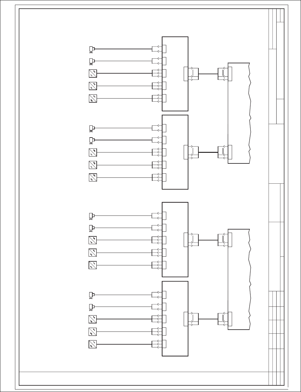
Wiring for PCB dual conveyor
00119462-010202LD3
Cable: incremental encoder, track B
Limit switch, lifting table
Cable: incremental encoder, track A
Cable: valve f. lifting table down
Cable: valve f. lifting table up
Cable: incremental encoder, track B
Limit switch, lifting table
Cable: incremental encoder, track A
Cable: valve f. lifting table down
Cable: valve f. lifting table up
Cable: incremental encoder, track B
Limit switch, lifting table
Cable: incremental encoder, track A
Cable: valve f. lifting table down
Cable: valve f. lifting table up
Incremental encoder, track A, lifting table
Increme
ntal encoder, track B, lifting table
(upper fork light barrier)
(lower fork light barrier)
Cylinder switch
Lifting table, valve up ("14" connector)
Lifting table, valve down ("12" connector)
Incremental encoder, track A, lifting table
Incremental encoder, track B, lifting table
(upper fork light barrier)
(lower fork light barrier)
Cylinder switch
Lifting table, valve up ("14" connector)
Lifting table, valve down ("12" connector)
Incremental encoder, track A, lifting table
Increme
ntal encoder, track B, lifting table
(upper fork light barrier)
(lower fo
rk light barrier)
Cylinder switch
Lifting table, valve up ("14" connector)
Lifting table, valve down ("12" connector)
Conversion board, lifting table (track 1, PC1)
X6
00362766-xx
003630
79-xx
Cable: incremental encoder, track B
Limit switch, lifting table
Cable: incremental encoder, track A
Cable: valve f. lifting table down
Cable: valve f. lifting table up
00363080-xx
00363076-xx
00363078-xx
00363077-xx
Increme
ntal encoder, tra
ck A, lifting tab
le
Increme
ntal encoder, track B, lifting table
(upper fork light barrier)
(lower fo
rk light barrier)
Cylinder switch
Lifting table, valve up ("14" connector)
Lifting table, valve down ("12" connector)
X1 X2
Conversion board, lifting table (track 2, PC2)
00362766-xx
Lifting table, track 1, placement sector 1 Lifting table, track 2, placement sector 1
(lv)
(ly)
2
3
6
P24
GND
IN
2
3
6
P24
GND
IN
X3 X4 X5
2
6
GND
OUT
2
6
GND
OUT
2
3
6
P24
GND
IN
X6lv
X1kt
1
2
10
1
2
10
X1kt
X6
X6ly
X1ku
1
2
10
1
2
10
X1ku
Conversion board, lifting table, (track 1, PC2)
X6
00362766-xx
00363079-xx
00363080-xx
00363076-xx
00363078-xx
00363077-xx
X1 X2
Lifting table, track 1, placement sector 2
(lw)
2
3
6
P24
GND
IN
2
3
6
P24
GND
IN
X3 X4 X5
2
6
GND
OUT
2
6
GND
OUT
2
3
6
P24
GND
IN
X6lw
X2kt
1
2
10
1
2
10
X2kt
Conversion board, lifting table (track 2, PC2)
00362766-xx
Lifting table, track 2, placement sector 2
(lz)
X6
X6lz
X2ku
1
2
10
1
2
10
X2ku
00359425-xx
Conversion board, assembly trough (track 1)
(kt)
00359425-xx
Conversion board, assembly trough (track 2)
(ku)
00363438-xx
00363439-xx
00363440-xx
00363441-xx
00363079-xx
00363080-xx
00363076-xx
00363078-xx
00363077-xx
X1 X2
2
3
6
P24
GND
IN
2
3
6
P24
GND
IN
X3 X4 X5
2
6
GND
OUT
2
6
GND
OUT
2
3
6
P24
GND
IN
00363079-xx
00363080-xx
00363076-xx
00363078-xx
00363077-xx
X1 X2
2
3
6
P24
GND
IN
2
3
6
P24
GND
IN
X3 X4 X5
2
6
GND
OUT
2
6
GND
OUT
2
3
6
P24
GND
IN
6

6 Modular PCB conveyor system Service Manual HS-60
6.18 Final steps and functions test 03/2003 US Issue
246
6.18 Final steps and functions test
DANGER
During the following functions test, adhere strictly to the safety instructions in Chapter 2.
Æ If the cutter has been removed, you will have to reinstall it, as described in the service man-
ual, Chapter „Cutter, pneumatic“ (see safety instructions in the above mentioned chapter).
Æ If the nozzle changer has been removed, you will have to recalculate the nozzle changer
positions after the changer has been reinstalled (SITEST program).
Æ Remove all tools etc. from the working area of the machine.
Æ Carry out all necessary adjustments and a functions test, depending on how the problems
were solved:
– with the station software, transport menu / width adjustment system,
– with the aid of the SITEST program and according to the „Setting Instructions for HS-60“.