Service Manual HS60.pdf - 第129页
HS -60 Se rvic e Manu al 4 Ga ntr ies 03/ 2003 US Issu e 4.1 2 Repla ci ng th e lin ear m otor - prim ary par t (003 3314 8-0 2) 127 Æ Lo osen the nine M5 x 20 hexagon socket-head sc rews (i tem 3 in Fig. 4.12 - 3 ) an d…
4 Gantries HS-60 Service Manual
4.12 Replacing the linear motor - primary part (00333148-02) 03/2003 US Issue
126
4.12.4 Removing the primary part of the linear motor
Æ Remove the X-axis motor unit as described in Section 4.11.3, page 118 onward.
4
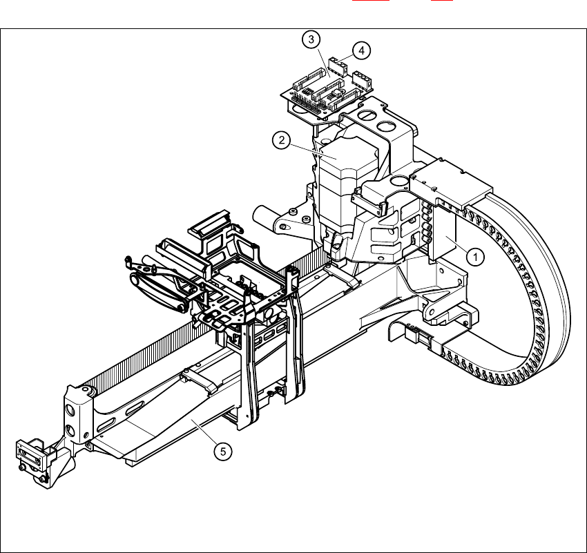
Fig. 4.12 - 2 Replacing the linear motor - primary part (1)
Key
(1) Linear motor - primary part
(2) X-axis motor unit
(3) X/Y distributor
(4) Socket X4 for the connecting cable of the primary part
(5) Gantry
4
HS-60 Service Manual 4 Gantries
03/2003 US Issue 4.12 Replacing the linear motor - primary part (00333148-02)
127
Æ Loosen the nine M5 x 20 hexagon socket-head screws (item 3 in Fig. 4.12 - 3) and remove the
primary part laterally (item 2 in Fig. 4.12 - 3
).
Æ Make sure that the lock rails will not drop.
4
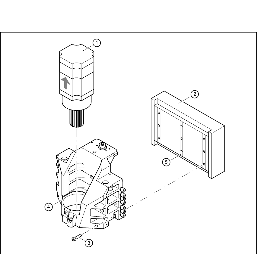
Fig. 4.12 - 3 Replacing the linear motor - primary part (2)
Key
(1) X-axis motor unit
(2) Linear motor - primary part
(3) 9 x M5 x 20 hexagon socket-head screws
(4) Motor bracket with press-fit connection (pneumatic system)
(5) Lockrail
4 Gantries HS-60 Service Manual
4.12 Replacing the linear motor - primary part (00333148-02) 03/2003 US Issue
128
4.12.5 Installing the primary part of the linear motor
Æ Fit scotch tape on the lower edge of the primary part of the linear motor to prevent the lockrails
from dropping.
Æ Push in the primary part from the side.
Æ Use the nine M5 x 20 hexagon socket-head screws (item 3 in Fig. 4.12 - 3) to fix the primary
part (item 2 in Fig. 4.12 - 3
) to the motor bracket (item 4 in Fig. 4.12 - 3).
Make sure that the primary part is aligned in parallel to the permanent magnet.
Æ Fit the X-axis motor unit as described in Section 4.11.4, page 121 onward.
Æ Fix all the cables with cable ties.
CAUTION 4
Make sure that the cables are firmly seated. Otherwise, the high acceleration forces may
cause the cable to slip out of position and shear through. 4
Æ Fit the permanent magnets (4 or 16 M6 x 12 hexagon socket-head screws).
Æ Fit the black cover strips on the cross-beam above the gantry concerned (3 M6 x 8 hexagon
socket-head screws).
4.12.6 Settings
Æ Use the belt tension measuring device to set the X-axis toothed belt tension to 53 Hz + 1/-3 Hz.
CAUTION 4
Do not overstretch the toothed belt when adjusting the belt tension. 4
Æ Secure the hexagon socket-head screw (item 2 in Fig. 4.11 - 1) with the locknut (item 8 in Fig.
4.11 - 1
).