Service Manual HS60.pdf - 第43页
Se rv ice M a nu al HS-6 0 2 Ope rati on al saf et y 03/ 200 3 U S Iss ue 2.4 Safe ty eq uipme nt 41 2.4. 2 Gua rd on th e input /outp ut be lt DANGER OF CRUSHING! 2 The gu ard m ust always be set to the hei ght of the c…
2 Operational safety Service Manual HS-60
2.4 Safety equipment 03/2003 US Issue
40
Function 2
If one of the protective covers has been swung upwards or one of the covers on the PCB conveyor
has been lifted, the power supply to the gantry axes is cut off immediately. The gantry axes stop
moving. The message "Close cover" is displayed on the screen. 2
Æ Close the protective covers and press one of the start buttons to continue placement.
2
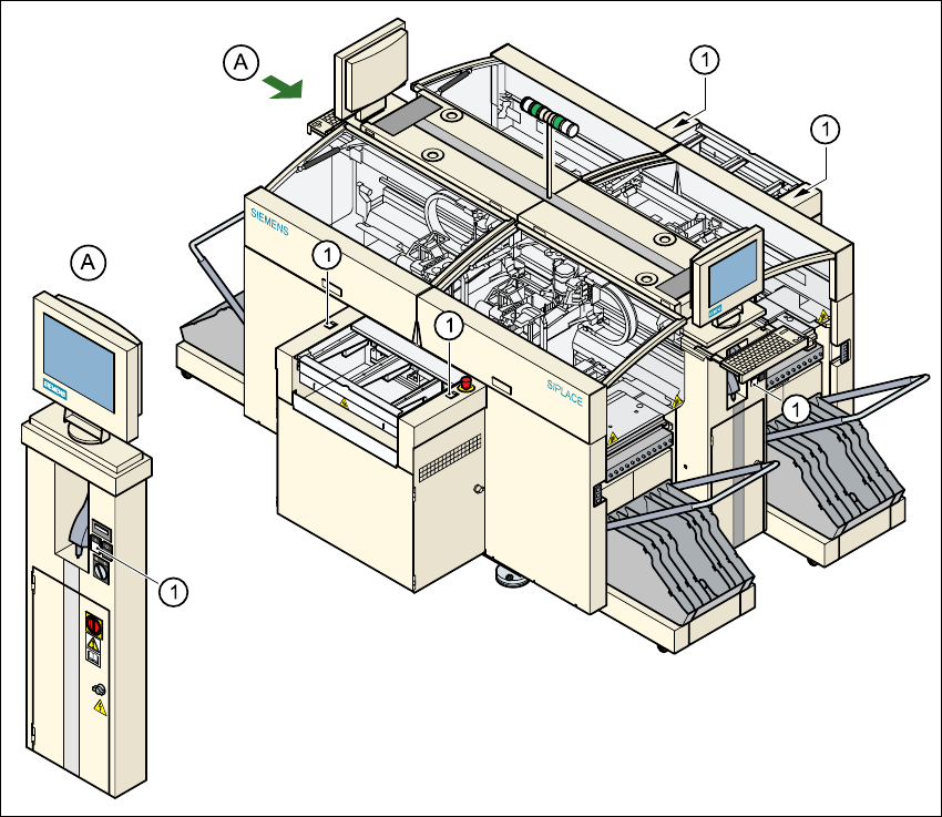
Fig. 2.4 - 2 Position of the Start button (white) on the machine
(1) Start button (white) on the machine
2
Service Manual HS-60 2 Operational safety
03/2003 US Issue 2.4 Safety equipment
41
2.4.2 Guard on the input/output belt
DANGER OF CRUSHING! 2
The guard must always be set to the height of the circuit board to be processed. The gap between
the guard and the safety bar should be kept as small as possible. The guard is mounted on the
input and output belts of the PCB conveyor. 2
Æ Never reach through the gap into the inside of the machine. There is a danger of crushing from
the lifting table.
Æ Adjust the height of the guard at the slots so that the circuit board to be processed can be car-
ried through.
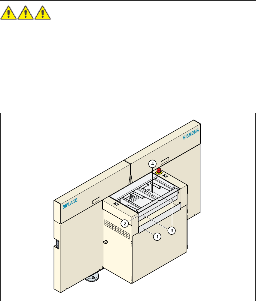
Fig. 2.4 - 3 Guard at the input and output belts of the machine
(1) Safety bar (fixed)
(2) Guard (adjustable)
(3) Slots for adjusting the height
(4) Cover
2 Operational safety Service Manual HS-60
2.4 Safety equipment 03/2003 US Issue
42
2.4.3 Main power switch, EMERGENCY-STOP mushroom-head push-button,
protective cover switch
2.4.3.1 Position of the main power switch, start buttons etc. on the machine
2
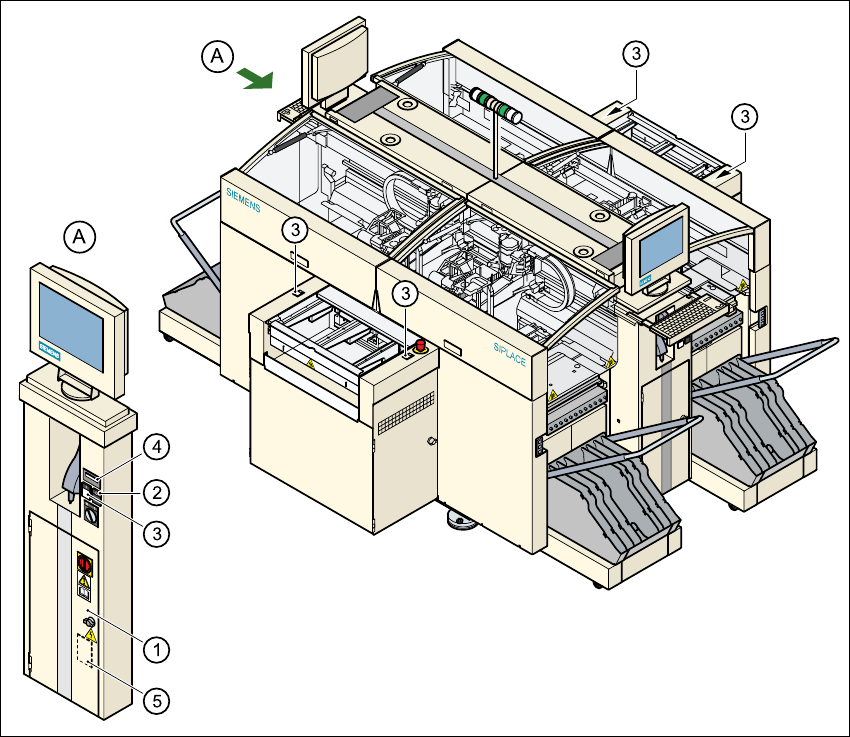
Fig. 2.4 - 4 Position of main switch, start buttons etc.
(1) Main power switch
(2) Stop button (black)
(3) Start button (white)
(4) Component counter
(5) Service socket in the power supply unit behind the safety door
2