Service Manual HS60.pdf - 第199页
Se rv ic e Ma nu al HS- 6 0 6 Mo du la r P C B c onve y or s y st em 03/ 2 003 U S I ss ue 6 .1 2 S ett in g t he fi xe d co nvey o r s id e (s in gl e an d dual co nv e yor ) 197 F ig. 6. 12. 20 S e tti ng th e "f …
6 Modular PCB conveyor system Service Manual HS-60
6.12 Setting the fixed conveyor side (single and dual conveyor) 03/2003 US Issue
196
NOTE:
It is not normally necessary to adjust the fixed conveyor side. An exception to this rule is when
service work requires prior movement of the fixed conveyor side.
Procedure:
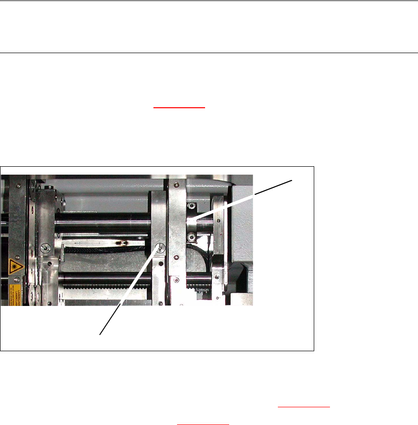
Æ Undo the fastening screw(1) (s. Fig. 6.12.19) on the side flange.
– The fastening screw also has a (1) hexagon socket-head grub screw, which you will need
to loosen slightly - do not unscrew it fully!
6
Fig. 6.12.19 Modular transport details
Æ Remove the fastening screw (1). Make sure you do not lose the spring inside.
Æ Push the fixed transport side as far as to the stop ring (2) (s. Fig. 6.12.19).
Æ Check the measurements in line with Fig. 6.12.20.
Æ Insert the spring and tighten the screw fastening the brake.
Æ First fasten one side flange with the fastening screw and check the measurements on both
sides Both conveyor sides must run parallel to one another
Æ Fasten the second side flange with the fastening screw and check the measurements again.
Æ Test run the PCB conveyor to a distance of 216 mm and move the test PCB
(item no. 00359535-01) in the PCB conveyor. The PCB must be moved through the entire PCB
conveyor system.
1
2
Service Manual HS-60 6 Modular PCB conveyor system
03/2003 US Issue 6.12 Setting the fixed conveyor side (single and dual conveyor)
197
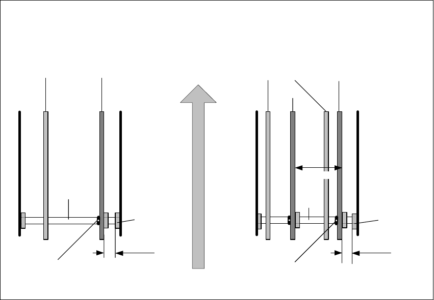
Fig. 6.12.20 Setting the "fixed conveyor side" HS-60, S-27 HM
Conveyor side walls
movable stationary
Dual conveyor
Conveyor side walls
track 2 track 1
Shaft
support
Single conveyor
Direction of PCB transport
Screw to loosen the
stationary wall
Screw to loosen the
stationary wall
movable
station.
stationary
34.5mm 30.5mm
251.7 mm
Shaft
Shaft
support
Shaft

6 Modular PCB conveyor system Service Manual HS-60
6.13 Width adjustment 03/2003 US Issue
198
6.13 Width adjustment
DANGER
Please observe the safety instructions in Chapter 2.
6.13.1 Function
The width adjustment system is motor-driven with program control. For dual conveyor systems,
differing widths can be set for the two conveyor tracks. The width adjustment uses a stepping mo-
tor, meaning that the PCB width can be set independently of other machine components (e.g. the
Y-gantry). There is no end position proximity switch at the side.
The conveyor width set is fixed to a steel strip, with the help of a clamping device.
The PCB width is adjusted via two adjustment units (pneumatic cylinders), installed under the in-
put or output conveyor.
– The stepping motor moves the two adjustment units synchronously through the use of ball
screws and a toothed belt.
– To adjust the PCB width, the two adjustment units are positioned under the conveyor side con-
cerned. The exact position is determined with the help of an end position proximity switch on
the relevant adjustment unit.
– The pneumatically operated fixing pins mechanically connect the conveyor side with the ad-
justment unit. The conveyor side is unclamped (on the steel strip).
– After the new PCB width has been set, the conveyor side is reclamped and the adjustment unit
fixing pins are disconnected.
For dual conveyor systems, the widths of the transport paths are set one after the other (only one
drive unit for both conveyor tracks). Maximum and minimum PCB widths are monitored by the end
position switch. If the two conveyor sides of any one conveyor track are not parallel to one another,
this will be automatically corrected during width adjustment. The two adjustment units are then
moved under the conveyor side concerned. The adjustment unit first reaching its position under
the conveyor side fixes this. Travel continues until the second adjustment unit has also reached
its position and fixed the conveyor side.
The conveyor track has now been corrected and the two conveyor sides should be parallel. If nec-
essary, the correct PCB width can now be set.