Service Manual HS60.pdf - 第40页
2 O per ati onal sa fety S er vice Ma nual H S- 60 2.3 Las er clas sifi cat ion 03/ 200 3 U S Iss ue 38 2.3. 8 Safety in struction s fo r the ta p e cut ter F ig. 2. 3 - 3 S afe ty in str u cti ons for the tape c ut ter …

Service Manual HS-60 2 Operational safety
03/2003 US Issue 2.3 Laser classification
37
Please follow the instructions given below to minimize the risk when placing capacitors based on
powdered metal.
(1) If the component tape is cycled onward manually, the operator must remove any components
remaining in the tape pocket.
(2) If the cover foil tears, the operator must remove any components remaining on the tape.
(3) The waste tape container must be emptied regularly (recommended interval: every hour).
The feeders are labeled as shown below:
CAUTION 2
CAUTION To avoid the risk, it is essential to use only feeders that have been approved for plac-
ing such components, namely:
for model C/D item no.:00141118-01
for model E item no.:00141117-01
WARNING FIRE HAZARD 2
Æ Check and empty the waste tape container every hour.
Æ Only empty the waste tape container into suitable collection containers because of the risk of
fire. These containers must not be set up inside buildings.
2
Approved for
capacitors based on
metal-powder
Freigegeben für
Kondensatoren auf
Metallpulver-Basis
2 Operational safety Service Manual HS-60
2.3 Laser classification 03/2003 US Issue
38
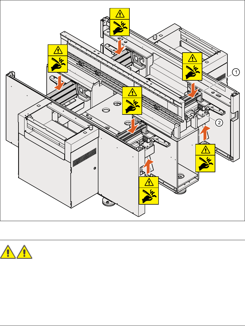
2.3.8 Safety instructions for the tape cutter
Fig. 2.3 - 3 Safety instructions for the tape cutter
WARNING RISK OF CUTTING! 2
Æ Never reach down into the used tape channel (Pos. (1)) from above with bare hands, even if
the machine is switched off.
Æ Similarly, even when the machine is switched off, do not reach up from below with bare hands
into the ejection opening of the tape cutter (Pos. 2), e.g. to remove waste used tape.
Æ To remove waste used tape, it is essential to switch the machine off first and put on very sub-
stantial protective gloves, as the tape cutter bars are extremely sharp.
Service Manual HS-60 2 Operational safety
03/2003 US Issue 2.4 Safety equipment
39
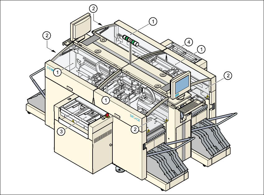
2.4 Safety equipment
2.4.1 Protective covers
2
Fig. 2.4 - 1 protective covers
2
The travelling range of the gantries has four protective covers that can be swung upwards. There
are side screens to prevent access to the inside of the machine from the side. Access to the PCB
conveyor is protected by coversby covers, which can be pivoted upwards, over the input and out-
put belts and guards on both belts. 2
(1) Protective covers
(2) Safety panels
(3) Cover and guard on the input belt
(4) Cover and guard on the output belt