Service Manual HS60.pdf - 第197页
Se rv ic e Ma nu al HS- 6 0 6 Mo du la r P C B c onve y or s y st em 03/ 2 003 U S I ss ue 6 .1 2 S ett in g t he fi xe d co nvey o r s id e (s in gl e an d dual co nv e yor ) 195 6.12 Setting the fixed conv eyor side (s…
6 Modular PCB conveyor system Service Manual HS-60
6.11 Lifting table 03/2003 US Issue
194
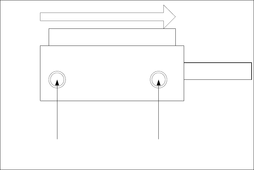
Abb. 6.11 - 17 Adjustment valves on the lifting table cylinder
– Rotating adjustment valve to the left: increases the lifting table travel time
– Rotating adjustment valve to the right: reduces the lifting table travel time
Valve setting
Time chracteristic for lifting table
below
Valve setting
Time chracteristic for lifting table
above
Transport direction
Pneumatic valve
Lifting table cylinder
Piston rod
Service Manual HS-60 6 Modular PCB conveyor system
03/2003 US Issue 6.12 Setting the fixed conveyor side (single and dual conveyor)
195
6.12 Setting the fixed conveyor side (single and dual
conveyor)
NOTE
After undoing the conveyor side fixtures you MUST check the settings for the fixed conveyor side.
If these values are not correctly set for single or dual conveyers, this could cause the placement
nest to shift out of position. This could again lead to errors in the fiducial recognition.
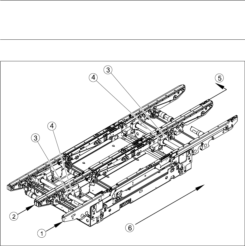
Fig. 6.12.18 Moving fixed conveyor side for conveyor track 2 (in example of S-27 HM)
Key
(1) Fixed side - conveyor track 1 (4) Fastening screw
(2) Fixed side - conveyor track 2 (5) Moving the fixed side - conveyor track 2
(3) Side flange with grub screw (6) Direction of travel
6 Modular PCB conveyor system Service Manual HS-60
6.12 Setting the fixed conveyor side (single and dual conveyor) 03/2003 US Issue
196
NOTE:
It is not normally necessary to adjust the fixed conveyor side. An exception to this rule is when
service work requires prior movement of the fixed conveyor side.
Procedure:
Æ Undo the fastening screw(1) (s. Fig. 6.12.19) on the side flange.
– The fastening screw also has a (1) hexagon socket-head grub screw, which you will need
to loosen slightly - do not unscrew it fully!
6
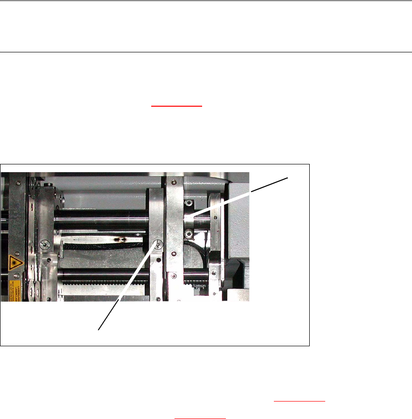
Fig. 6.12.19 Modular transport details
Æ Remove the fastening screw (1). Make sure you do not lose the spring inside.
Æ Push the fixed transport side as far as to the stop ring (2) (s. Fig. 6.12.19).
Æ Check the measurements in line with Fig. 6.12.20.
Æ Insert the spring and tighten the screw fastening the brake.
Æ First fasten one side flange with the fastening screw and check the measurements on both
sides Both conveyor sides must run parallel to one another
Æ Fasten the second side flange with the fastening screw and check the measurements again.
Æ Test run the PCB conveyor to a distance of 216 mm and move the test PCB
(item no. 00359535-01) in the PCB conveyor. The PCB must be moved through the entire PCB
conveyor system.
1
2