Service Manual HS60.pdf - 第53页
Se rv ice M a nu al HS-6 0 2 Ope rati on al saf et y 03/ 200 3 U S Iss ue 2.4 Safe ty eq uipme nt 51 2 F ig. 2. 4 - 7 S af ety cir cu its Com p res sed ai r min. 0.5 MP a (5.0 bar)? No St art bu tto n pre ss ed Eme rg. s…
2 Operational safety Service Manual HS-60
2.4 Safety equipment 03/2003 US Issue
50
– 24 V operating voltage is switched to the used tape cutters.
The machine is then ready for use. 2
Service Manual HS-60 2 Operational safety
03/2003 US Issue 2.4 Safety equipment
51
2
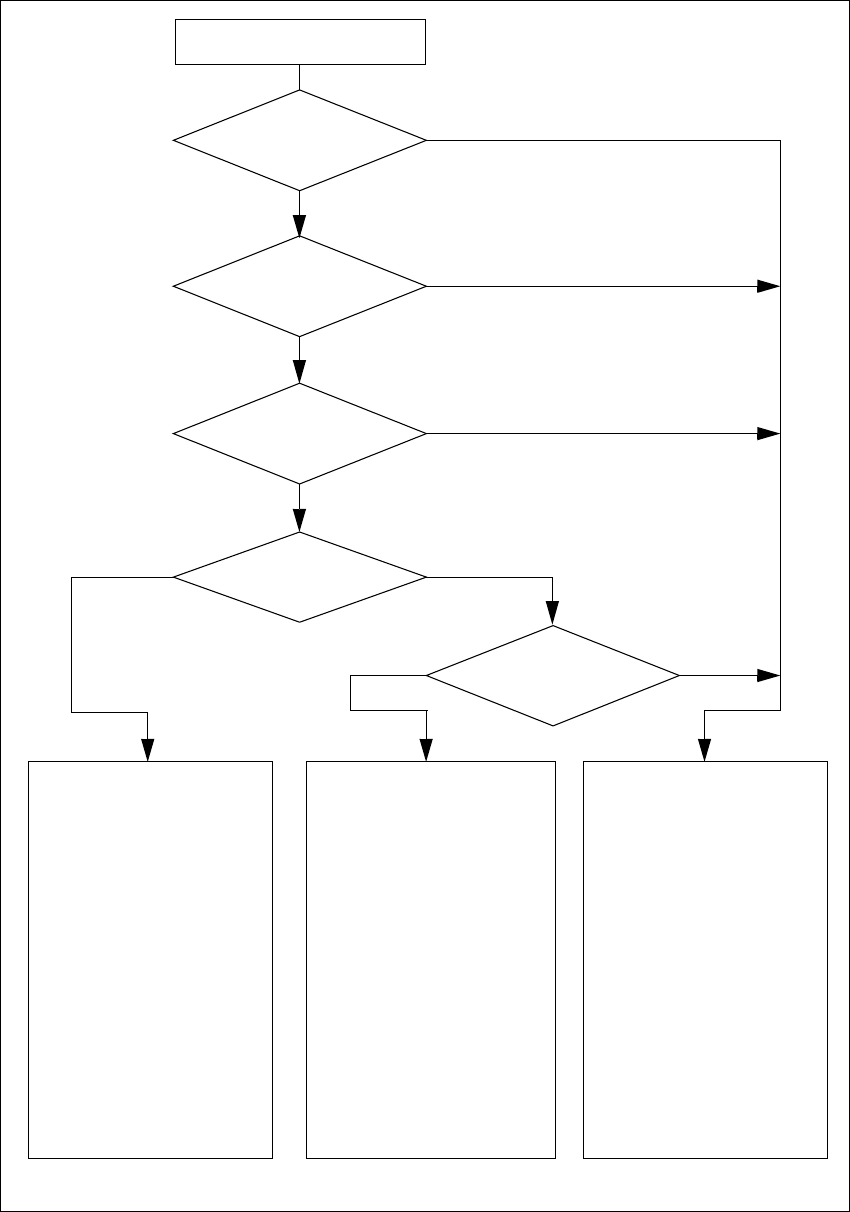
Fig. 2.4 - 7 Safety circuits
Compressed air
min. 0.5 MPa
(5.0 bar)?
No
Start button pressed
Emerg. stop
mushroom-head push-but-
ton pressed?
Protective cover open ?
Key switch
closed (positionI)?
No
Component table
safety circuit
interrupted?
Yes
No
No
Yes
Yes
No
Active
PCC*) yes
voltage
Y-axis 200 V
X-axis 200 V
Star axis 100 V
DP-axis 30 V
Z-axis 30 V
Active
PCB conveyor yes
Lifting table yes
PCB clamping yes
Width adjustment yes
Laser light barrier yes
Used tape cutter yes
Yes
Active
PCC*) no
voltage
Y-axis 0 V
X-axis 0 V
Star axis 6 V
DP-axis 30 V
Z-axis 30 V
Active
PCB conveyor yes
Lifting table no
PCB clamping no
Width adjustment yes
Laser light barrier no
Used tape cutter no
Active
PCC*) no
voltage
Y-axis 0 V
X-axis 0 V
Star axis 10 V
DP-axis 30 V
Z-axis 30 V
Active
PCB conveyor no
Lifting table no
PCB clamping no
Width adjustment no
Laser light barrier no
Used tape cutter no
*) PCC protective contactor combination
yes
2 Operational safety Service Manual HS-60
2.4 Safety equipment 03/2003 US Issue
52
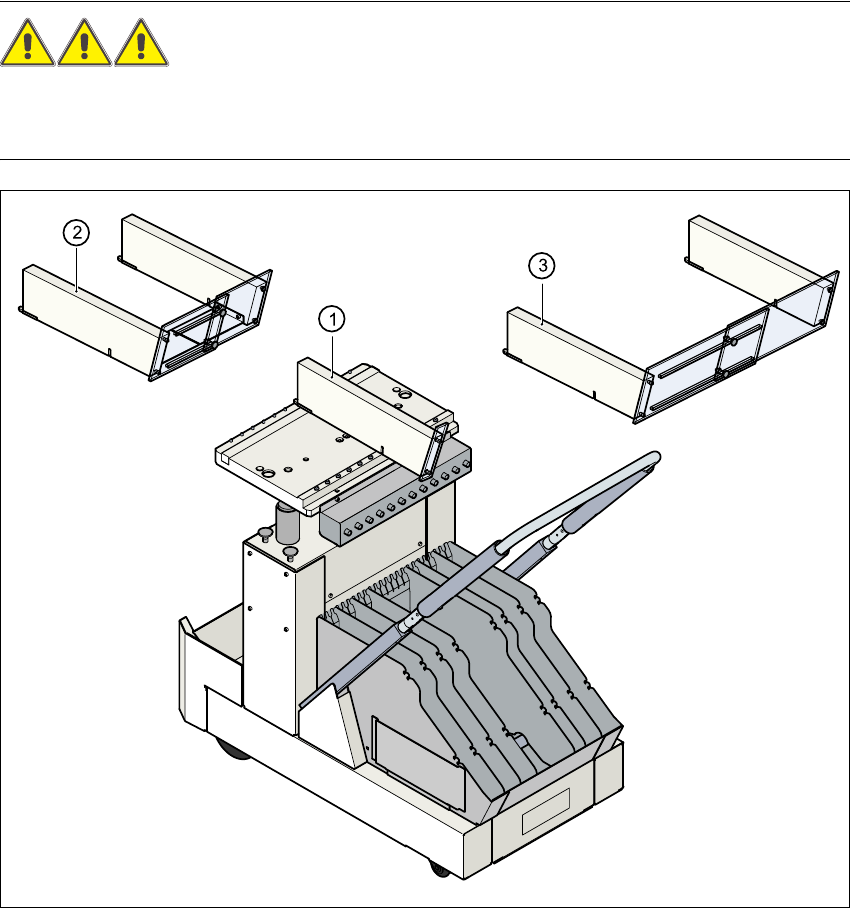
2.4.5 Guard on the component table locations
DANGER 2
All locations must be equipped with feeders in order to guarantee operational reliability.If there
are not enough feeders available, a guard ("dummy feeder") must be fitted in place of the feeder.
Fig. 2.4 - 8 Guard on the CO trolley
(1) Guard for 1 location item no. 00116820-01
(2) Guard for 6 to 10 locations item no. 00116821-01
(3) Guard for 11 to 20 locations item no. 00116822-01