Service Manual HS60.pdf - 第162页
6 Modu lar PCB conv eyor syste m Ser vic e Manu al HS- 60 6. 5 F unc tio n 03/ 200 3 U S Iss ue 160 – The placem ent rate no l onger depends on the thickness of t h e PCB. – The recognit ion of P CB f iducials i s optim …
Service Manual HS-60 6 Modular PCB conveyor system
03/2003 US Issue 6.3 Parts
159
6.3 Parts
For spare part item numbers and diagrams please refer to the HS 60 spare parts catalog.
6.4 Tools, testing aids, documentation
– 1 set of Allen wrenches
– Slotted and cross-slotted screwdriver, size 1
– Small rubber mallet
– 1 diagonal-nosed wire cutters, small
–Cable ties
– Set of open-end wrenches, width across flats 5.5 and 8
– 1 digital voltmeter (class 1.5)
– Shim to adjust the guide rails.
– Caliper gauge and feeler gauge, 0.2 mm
– Various gauge blocks
– Current spare parts catalog for SIPLACE HS-60 and folder of circuit diagrams for SIPLACE
HS-60
– SITEST program including current operating instructions for SITEST program
– Current documentation „Adjusting instructions for HS-60“
6.5 Function
6.5.1 General
The standard machine is equipped as a single PCB conveyor. A dual PCB conveyor system is
optionally available. Depending on individual requirements, either the left or right conveyor side
can be selected as the fixed conveyor side.
During placement, the PCB is clamped in place from underneath.The gap between the upper side
of the PCB and the placement head is not dependent on the thickness of the PCB and therefore
remains constant. This has the following benefits:
6 Modular PCB conveyor system Service Manual HS-60
6.5 Function 03/2003 US Issue
160
– The placement rate no longer depends on the thickness of the PCB.
– The recognition of PCB fiducials is optimized.
The constant distance between the PCB upper edge and the PCB camera means that the PCB
camera is always focussed clearly on the PCB surface. The PCB fiducial are always optimally
displayed on the CCD chip of the PCB camera.
PCB conveyor systems are configured within the machine so that, with the 12-segment col-
lect&place head, placement can be performed on components to a maximum height of 6 mm and,
with the 6-segment collect&place head (S-27 HM), on components to a max. of 8.5 mm.
The transport height can be set to allow the machines to be integrated into lines with 830, 900,
930 or 950 mm transport height. Communication between the PCB conveyors of the individual
machines is possible via either a SIEMENS or SMEMA interface.
PCB transport is monitored and controlled by light barriers, consisting of both a transmitter and
receiver module:
– Once a PCB reaches the placement area, it is recognized by a light barrier and the speed of
the conveyor belt is reduced.
– Approximately 100 ms later, the front edge of the slowly progressing PCB is detected by a laser
beam and the PCB is stopped and clamped in placed from underneath.
Service Manual HS-60 6 Modular PCB conveyor system
03/2003 US Issue 6.6 Overview
161
6.6 Overview
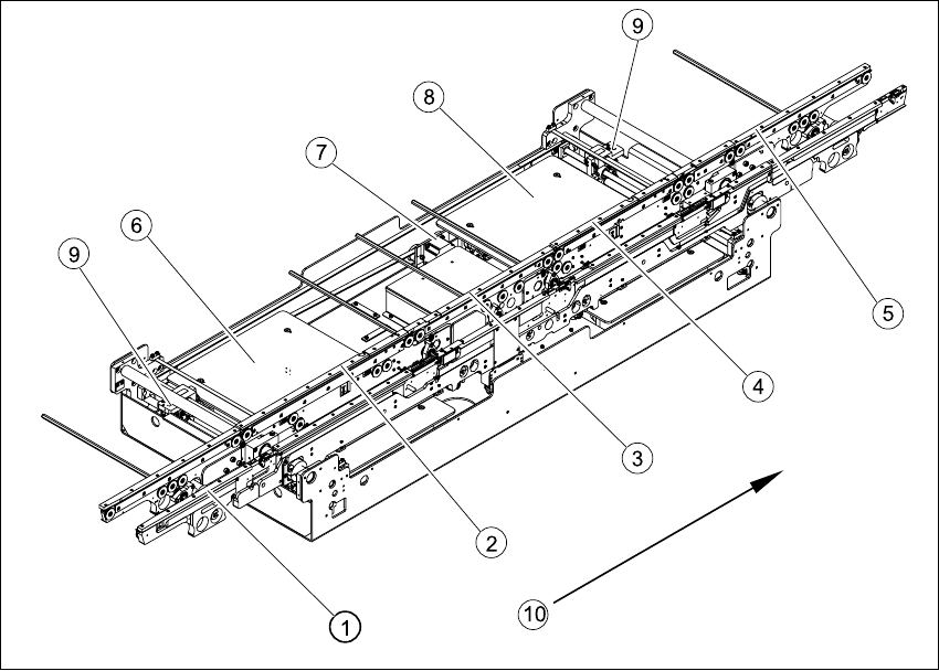
6.6.1 Single conveyor system
The HS-60 single conveyor system consists of an input conveyor, two placement areas, the inter-
mediate conveyor and the output conveyor. The S-27 HM has only one placement area. In this
case, the single conveyor system consists of input conveyor, placement area and output con-
veyor. Each conveyor system has automatic width adjustment and a lifting table for clamping the
PCB in place.
Fig. 6.6.1 Overview - modular conveyor system (single conveyor)
Key
(1) Input conveyor (6) Lifting table placement area 1
(2) Placement area 1 (7) Width adjustment drive unit
(3) Intermediate conveyor (8) Lifting table placement area 2
(4) Placement area 2 (9) Width adjustment for adjustment units 1
and 2
(5) Output conveyor (10) Direction of transport