Service Manual HS60.pdf - 第55页
Se rv ice M a nu al HS-6 0 2 Ope rati on al saf et y 03/ 2003 US Is sue 2. 5 Re sidu al vol tage s and dis charge time s in th e machin e 53 2.5 Resid ual volt ages and disch arge times in the machine If the EMERGE NCY -…
2 Operational safety Service Manual HS-60
2.4 Safety equipment 03/2003 US Issue
52
2.4.5 Guard on the component table locations
DANGER 2
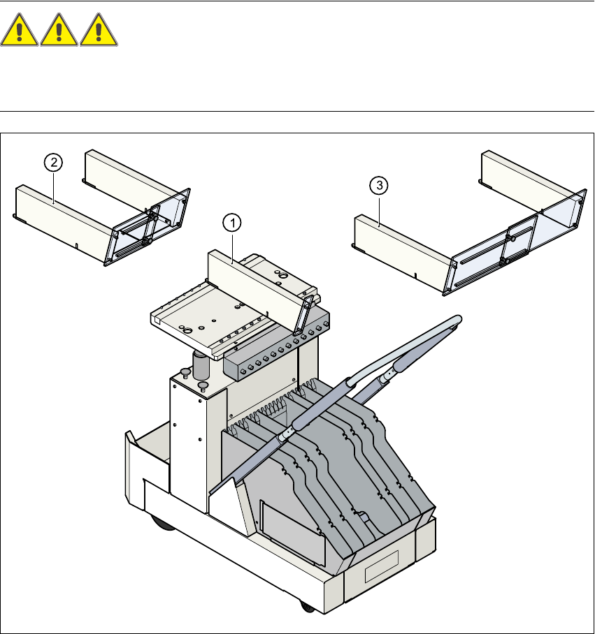
All locations must be equipped with feeders in order to guarantee operational reliability.If there
are not enough feeders available, a guard ("dummy feeder") must be fitted in place of the feeder.
Fig. 2.4 - 8 Guard on the CO trolley
(1) Guard for 1 location item no. 00116820-01
(2) Guard for 6 to 10 locations item no. 00116821-01
(3) Guard for 11 to 20 locations item no. 00116822-01
Service Manual HS-60 2 Operational safety
03/2003 US Issue 2.5 Residual voltages and discharge times in the machine
53
2.5 Residual voltages and discharge times in the
machine
If the EMERGENCY-STOP mushroom-head push-button is pressed or the placement system is
switched off, the 200 V link voltage for the gantry axes and the 100 V link voltage for the star axes
are discharged to harmless residual voltages in a very short time.
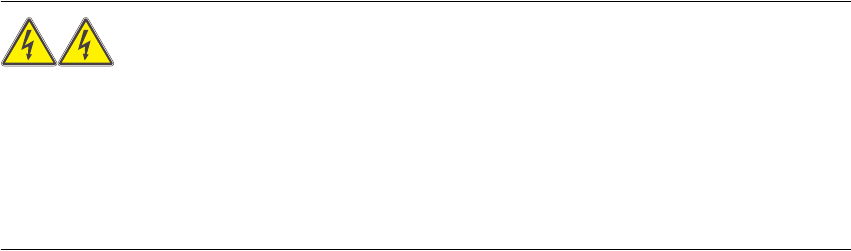
The voltages can be tapped off at test sockets X1 - X4 on the voltage measuring unit in the servo
unit. 2
WARNING 2
The placement system is supplied with 3 x 204 VAC (US version), 3 x 230 VAC, 3 x 380 VAC,
3 x 400 VAC or 3 x 415 VAC ± 5 %, 50/60 Hz main power voltage. This means that some parts of
the system carry potentially lethal voltages - even when switched off at the main power
switch.Death, serious injury or considerable damage may result if this automatic placement sys-
tem is handled incorrectly.
Æ Always follow the applicable accident prevention and DIN regulations (particularly DIN EN 60
204, part 1).
Æ The guard over the servo unit must ONLY be opened by appropriately qualified and trained
personnel.
2 Operational safety Service Manual HS-60
2.5 Residual voltages and discharge times in the machine 03/2003 US Issue
54
Fig. 2.5 - 1 Test sockets on the voltmeter unit in the servo unit
(1) Position of the servo unit
(2) Voltage measuring unit on the servo unit
2.5.1 Operating voltages, residual voltages and discharge times after pressing
the emergency stop mushroom-head push-button
2
Test sockets X2, X3, X4
measured to X1 (GND) Voltage in normal mode
Residual voltage after
EMERG. STOP Discharge times
X2 + 30 VDC + 30 VDC -
X3 + 100 VDC < 10 VDC 50 sec.
X4 + 200 VDC < 10 VDC 7 sec.