Service Manual HS60.pdf - 第291页
HS -60 Se rvic e Ma nual 7 DLM2 Co l lect&Plac e Head 03/ 2003 US Issu e 7.1 0 Rep laci ng th e int erme diate d istri but ion bo ard (003 3064 8-0 5) 289 Æ Ca refully remove the hose fr o m the pressure sensor (see …
7 DLM2 Collect&Place Head HS-60 Service Manual
7.10 Replacing the intermediate distribution board (00330648-05) 03/2003 US Issue
288
7.10.3 Dismantling the intermediate distribution board
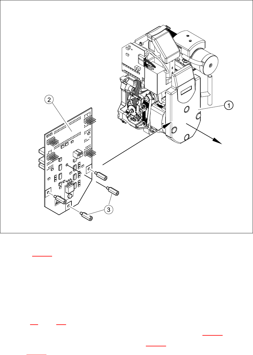
Fig. 7.10 - 1 Dismantling the intermediate distribution board
Key to Fig. 7.10 - 1
(1) Cover
(2) Intermediate distribution board
(3) 4 x M3x10 spacer bolt
7
Æ Switch the placement system off and secure it to prevent switching on again as described in
Section 7.4
, page 261.
Æ Remove the four mounting bolts and remove the cover (see item 1 in Fig. 7.10 - 1).
Æ Remove the four M3x10 spacer bolts (item 3 in Fig. 7.10 - 1) and tilt the PCB slightly (item 2
in Fig. 7.10 - 1
).
HS-60 Service Manual 7 DLM2 Collect&Place Head
03/2003 US Issue 7.10 Replacing the intermediate distribution board (00330648-05)
289
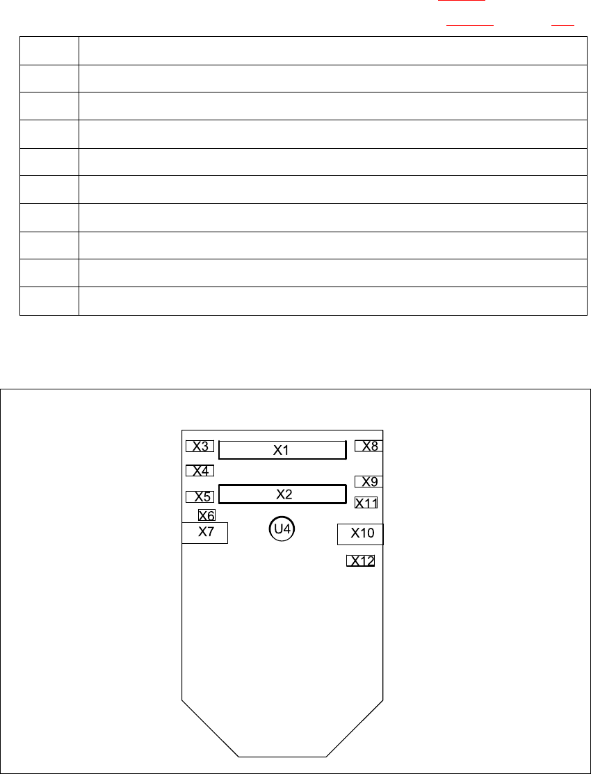
Æ Carefully remove the hose from the pressure sensor (see U4 in Fig. 7.10 - 2).
Æ Remove the following plugs from their sockets on the board (see Fig. 7.10 - 2 on page 289).
Æ Remove the intermediate distribution board.
7
Fig. 7.10 - 2 Sockets on the intermediate distribution board
X1 Ribbon cable at X14 on the head board
X2 Ribbon cable at X13 on the head board
X3 Motor / tacho connection for the Z-axis
X4 Measuring system connection for the Z-axis
X5 Motor connection for the star axis
X6 Connection for the "Forced air unit" valve
X7 Measuring system connection for the DP-axis
X10 Connection for the "Z-axis up" light barrier (adjustment unit)
X11 Connection for the "Z-axis down" light barrier
X12 Measuring system connection for the star axis
Tab. 7.10 - 1Sockets on the intermediate distribution board

7 DLM2 Collect&Place Head HS-60 Service Manual
7.11 Replacing light barrier ’Z-axis up’ (00347297-01) 03/2003 US Issue
290
7.10.4 Fitting the intermediate distribution board
Æ Restore connections X1 ... X12 as described in Table 7.10 - 1.
Æ Push the hose onto the pressure sensor tube (see item 4 in Fig. 7.10 - 1).
Æ Fix the intermediate distribution board in place (see item 2 and 3 in Fig. 7.10 - 1).
Æ Fix the protective cover to the head.
Æ Switch the placement system on and start it up.
7.10.5 Settings
No settings are required. 7
7
7.11 Replacing light barrier ’Z-axis up’ (00347297-01)
7.11.1 Tools and equipment
– Set of DIN 911 Allen keys
– Set of Phillips screwdrivers
– SITEST program
7.11.2 Parts
Light barrier ’Z-axis up’, item no. 00347297-01 7
7.11.3 Dismantling the ’Z-axis up’ light barrier
Æ Switch the placement system off and secure it to prevent switching on again as described in
Section 7.4
, page 261.
Æ Remove the plug from socket X10 on the intermediate distribution board (see item 10 in Fig.
7.2 - 5
, page 254).
Æ Undo the two M2.0x4 hexagon socket-head screws (see item 1 in Fig. 7.11 - 1) and remove
the ribbon cable clamp (see item 2 in Fig. 7.11 - 1
).
Æ Undo the two M1.6x3 Phillips screws (see item 3 in Fig. 7.11 - 1).
Æ Remove the light barrier board (see item 4 in Fig. 7.11 - 1) together with its cable.