Service Manual HS60.pdf - 第97页
HS -60 Se rvic e Manu al 4 Ga ntr ies 03/ 200 3 U S Iss ue 4. 2 S truc tu re of th e gan tr y 95 The sev en power cables take the form of f lexible ribbon cabl es, fou r of which are n eeded for the collect&pla ce he…
4 Gantries HS-60 Service Manual
4.2 Structure of the gantry 03/2003 US Issue
94
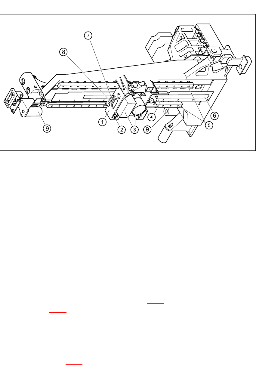
Figure 4.2 - 2
shows a bottom view of the gantry. 4
4
Fig. 4.2 - 2 Structure of the gantry - bottom view
Key
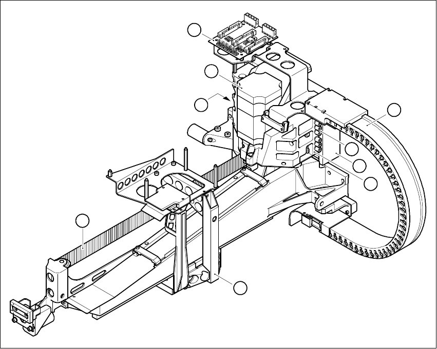
The gantry is fixed to the two shuttles (see item 1 in Fig. 4.2 - 3
) of the recirculating ball screw unit
(see item 2 in Fig. 4.2 - 3
) using four M6 x10 hexagon socket-head screws. 4
The secondary part (see item 3 in Fig. 4.2 - 3
) of the Y-axis linear drive, with its permanent mag-
nets, is located above the guide rail of the recirculating ball screw unit. The secondary part is
mounted on the machine frame. 4
The air and power supply and signal lines for the gantry and collect&place head all run in a trailing
cable (see item 1 in Fig. 4.2 - 4
). 4
(1) Head mount
(2) X-axis brake
(3) PCB camera with lens system
(4) Incremental encoder for the X-axis
(5) Recirculating ball screw unit KUME 12B
(6) Scale for the X-axis
(7) End position proximity switch 2
(8) End position proximity switch 1 and reference point for the X-axis
(9) Elastomeric spring 25x10.5x50
HS-60 Service Manual 4 Gantries
03/2003 US Issue 4.2 Structure of the gantry
95
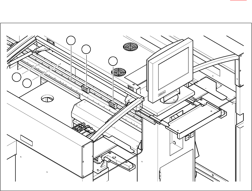
The seven power cables take the form of flexible ribbon cables, four of which are needed for the
collect&place head. They run beneath the cover in the machine frame (see item 1 in Fig. 4.2 - 5
),
between the head board on the head mount and the gantry board. 4
4
Fig. 4.2 - 3 Y-axis of the gantry
Key
(1) Shuttles of the recirculating ball screw unit for the Y-axis
(2) Guide rail of the recirculating ball screw unit for the Y-axis
(3) Secondary part of the linear drive for the Y-axis (permanent magnets)
(4) Scale for the Y-axis
4
4
3
1
1
2
4 Gantries HS-60 Service Manual
4.2 Structure of the gantry 03/2003 US Issue
96
4
Fig. 4.2 - 4 Trailing cable for gantry 1 and 3
Key
(1) Trailing cable
(2) X/Y distributor
(3) Primary part of the linear drive
(4) Head mount
(5) Three-phase AC motor for the X-axis
(6) Toothed belt for the X-axis
(7) Compressed air inlet couplings
(8) Compressed air outlet coupling
(9) Motor bracket
6
5
4
1
2
3
8
9
7