Service Manual HS60.pdf - 第266页
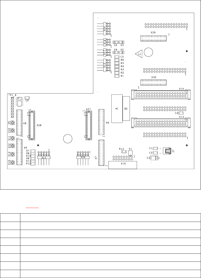
7 DL M2 Co llec t &P lace Head H S-6 0 S erv ic e Manu al 7. 5 R ep la cing th e c o lle c t&p la ce h ead / DLM 2 ( 0 0367 77 0-0 1) 03/ 2 003 U S I ss ue 264 7 F ig. 7. 5 - 1 He ad b oar d - p lug- in c o nn ec…

HS-60 Service Manual 7 DLM2 Collect&Place Head
03/2003 US Issue 7.5 Replacing the collect&place head / DLM2 (00367770-01)
263
7.5 Replacing the collect&place head / DLM2
(00367770-01)
7.5.1 Tools and equipment
– Set of DIN 911 Allen keys
– Setting instructions
– SITEST program
7.5.2 Parts
Collect&place head SP 12 complete / DLM2, item no. 00367770-01 7
7.5.3 Dismantling the collect&place head
– Switch the placement system off and secure it to prevent switching on again as described in
Section 7.4
, page 261.
– Detach the plug-in connections on the head board 00331451-xx (see Fig. 7.5 - 1
).
7 DLM2 Collect&Place Head HS-60 Service Manual
7.5 Replacing the collect&place head / DLM2 (00367770-01) 03/2003 US Issue
264
7
Fig. 7.5 - 1 Head board - plug-in connections
Key to Fig. 7.5 - 1
X9 For the component illumination controller and component camera
X10 For the vacuum measuring board
X12 For the DP-axis, motor and tacho
X13 For plug X2 on the intermediate distribution board
X14 For plug X1 on the intermediate distribution board
X18 For the infeed motor of the DP-axis
X19 For the "Placement circuit" valve positioning drive (star station 1)
X20 For the "Reject circuit" valve positioning drive (star station 3)
Tab. 7.5 - 1 Plug-in connections on the head board
HS-60 Service Manual 7 DLM2 Collect&Place Head
03/2003 US Issue 7.5 Replacing the collect&place head / DLM2 (00367770-01)
265
7
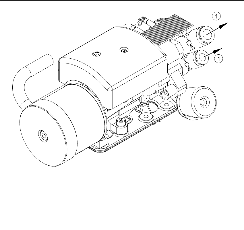
Fig. 7.5 - 2 Collect&place head - compressed air connections
Key to Fig. 7.5 - 2
(1) Compressed air connections
7
Æ Remove the black compressed air hose (1) from the compressed air connector.