Service Manual HS60.pdf - 第94页
4 G ant ri es HS- 6 0 S erv ice Ma nu al 4. 1 Ov e rvi ew 03/ 200 3 US I ssue 92 The st ructure of the gantries m akes them very torsional ly rigid. P recise mec hanical movements of the axes are produced by axis re circ…
HS-60 Service Manual 4 Gantries
03/2003 US Issue 4.1 Overview
91
4Gantries
4.1 Overview
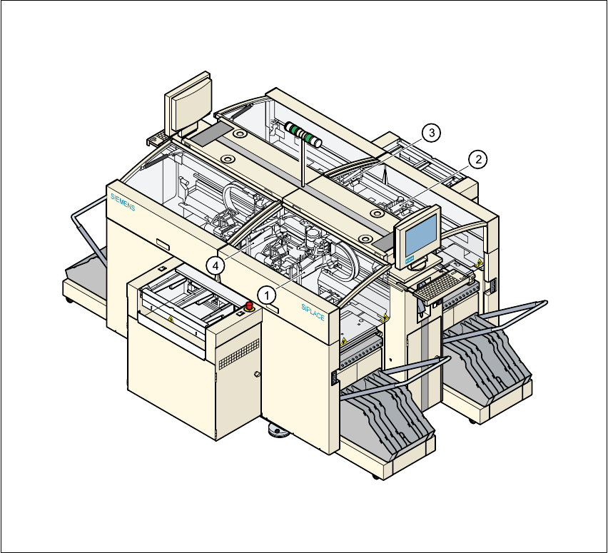
The placement system is equipped with four gantries. These enable the four collect&place heads
to be positioned in the x and y directions with great accuracy and independently of one another.4
4
Fig. 4.1 - 1 Gantries on the placement system
Key
(1) Gantry 1 (2) Gantry 2
(3) Gantry 3 (4) Gantry 4
4 Gantries HS-60 Service Manual
4.1 Overview 03/2003 US Issue
92
The structure of the gantries makes them very torsionally rigid. Precise mechanical movements
of the axes are produced by axis recirculating ball screw units. 4
High-precision positioning systems determine the positions of the x and y axes. To do this, the
graduations on metal scales are optoelectronically scanned and the track signals are sent to the
axis control in the control unit. 4
Direct drive units are used to position the placement heads in the x and y directions. This elimi-
nates friction losses, for example, which are typical when complex gearing is used. In addition,
there is none of the wear that can significantly affect the accuracy of positioning systems over the
course of time. 4
X-axis drive 4
A toothed belt is used to convert the rotary movement of the turning motor for the X-axis directly
into a translatory movement of the placement head in the x direction. 4
Y-axis drive 4
The translatory movement of the placement head in the y direction is generated by a linear mo-
tor. 4
HS-60 Service Manual 4 Gantries
03/2003 US Issue 4.2 Structure of the gantry
93
4.2 Structure of the gantry
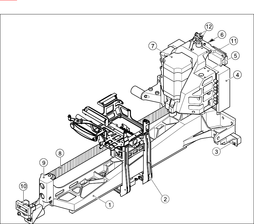
The principal element of the gantry is the torsionally rigid precision-cast gantry. Figure
4.2 - 1
contains a plan view of its major components. 4
4
Fig. 4.2 - 1 Structure of the gantry - plan view
Key
(1) Precision-cast gantry (2) Head mount
(3) Incremental encoder for Y-axis scale (4) Primary part of the y linear motor
(5) Motor bracket (6) Thrust bearing
(7) X-axis motor unit (8) Toothed belt
(9) Deflection unit (10) Y-axis brake, external
(11) Y-axis brake, internal (12) Proximity switches B1 and B2 for the Y-
axis