Service Manual HS60.pdf - 第319页
HS -60 Se rvic e Ma nual 7 DLM2 Co l lect&Plac e Head 03/ 2 0 03 US Is sue 7. 19 Repl acin g the "Z-ax is dow n" se nsor (0 0321 524- 05) 317 7.19 Rep la cin g th e "Z- axis do wn " se ns or (003 …
7 DLM2 Collect&Place Head HS-60 Service Manual
7.18 Replacing the RSF digital rotary encoder 12/DLM2 (00335990-02) 03/2003 US Issue
316
7
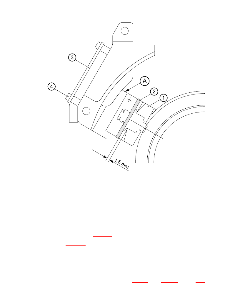
Fig. 7.18 - 2 Setting the distance between the rotary encoder window and the incremental disk
of the sleeve to 1.5 mm
– Remove the gauge for the star.
– Remove the sleeve from the star.
– Fix the RSF board (item 3 in Fig. 7.18 - 2
) in place using the two M2.5x4 hexagon socket-head
screws (item 4 in Fig. 7.18 - 2
).
– Connect the plug connector to socket X7 on the intermediate terminal block.
– Place the black blanking cap over the RSF board.
– Fit and adjust the star as described in Sections 7.16.4
and 7.16.5, page 306 onwards.
– Fit the front part of the collect&place head as described in Section 7.6.3
, page 272 onwards.
7.18.5 Adjustments
Æ Use the SITEST program to check that the rotary encoder is working correctly.

HS-60 Service Manual 7 DLM2 Collect&Place Head
03/2003 US Issue 7.19 Replacing the "Z-axis down" sensor (00321524-05)
317
7.19 Replacing the "Z-axis down" sensor (00321524-05)
7.19.1 Tools and equipment
– Set of DIN 911Allen keys
– Set of Phillips screwdrivers
– Drill, Ø 1,0 mm
– Gauge for the star (collect&place head / DLM2), article no. 00326164-01
– Power pack for collect&place head / DLM2, article no. 00353277-01
7.19.2 Parts
Sensor for "z-axis down", article no. 00321524-05 7
7.19.3 Removing the "Z-axis down" sensor
Æ Dismantle the front part of the collect&place head, as described in Section 7.6.2 page 269.
Æ Place the front part of the collect&place head on the tray.
Æ Dismantle the star, as described in Section 7.16.3 page 304.
Æ Remove the plug connector from socket X11 on the intermediate distribution board
(see Fig. 7.10 - 2
).
7
7 DLM2 Collect&Place Head HS-60 Service Manual
7.19 Replacing the "Z-axis down" sensor (00321524-05) 03/2003 US Issue
318
7
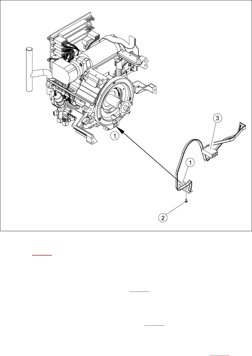
Fig. 7.19 - 1 Removing/installing the "z-axis down" sensor
Key to Fig. 7.19 - 1
(1) "Z-axis down" sensor
(2) Fixtures for sensor
(3) Plug for intermediate distribution board (see 7.10 - 2
)
7
Æ Push the z-axis down.
Æ Loosen the screw holding the sensor (item 2 in Fig. 7.19 - 1).
Æ Remove the cable clamps on the driver arm and star motor.
Æ Carefully pull the sensor and cable out of the front part of the collect&place head and remove
the plug (item 3) from socket X11 on the intermediate distribution board (see 7.10 - 2
).