Service Manual HS60.pdf - 第316页
7 DL M2 Co llec t &P lace Head H S-6 0 S erv ic e Manu al 7. 18 R e plac in g t he RS F di gi tal ro ta ry en co de r 1 2/ DLM 2 (00 33 59 90- 0 2) 03/2 00 3 U S I ss ue 314 7 F ig. 7. 18 - 1 Di sm ant lin g / fi tti…

HS-60 Service Manual 7 DLM2 Collect&Place Head
03/2003 US Issue 7.18 Replacing the RSF digital rotary encoder 12/DLM2 (00335990-02)
313
7.18 Replacing the RSF digital rotary encoder 12/DLM2
(00335990-02)
7.18.1 Tools and equipment
– Set of DIN 911 Allen keys
– Gauge for the star (collect&place head / DLM2), article number 00326164-01
– Test probe, 1.5 mm, article number 00326161-01
– Power pack for the collect&place head / DLM2, article number 00353277-01
– Tray for transporting the collect&place head
– Laboratory gloves
7.18.2 Parts
RSF digital rotary encoder 12/DLM2 article number 00335990-02 7
7.18.3 Dismantling the rotary encoder
– Dismantle the front part of the collect&place head as described in Section 7.6, page 269
onwards.
– Dismantle the star as described in Section 7.16.3
, page 304 onwards.
– Remove the black blanking cap over the RSF board (item 4 in Fig. 7.18 - 1
).
– Remove the plug connector (item X7 in Fig. 7.18 - 1
) from socket X7 on the intermediate
terminal block.
– Undo the two M2.5x4 hexagon socket-head screws (item 5 in Fig. 7.18 - 1
) for fixing the RSF
board.
– Undo the two M2.5x8 hexagon socket-head screws (item 3 in Fig. 7.18 - 1
) and remove the
rotary encoder.
7 DLM2 Collect&Place Head HS-60 Service Manual
7.18 Replacing the RSF digital rotary encoder 12/DLM2 (00335990-02) 03/2003 US Issue
314
7
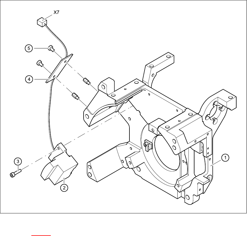
Fig. 7.18 - 1 Dismantling / fitting the rotary encoder
Key to Fig. 7.18 - 1
(1) Front part of collect&place head
(2) RSF digital rotary encoder 12/DLM2
(3) M2.5x8 hexagon socket head screws, 2x
(4) RSF board, type 950
(5) M2.5x4 hexagon socket head screws, 2x
X7Plug connector in socket X7 on the intermediate terminal block 7
7
HS-60 Service Manual 7 DLM2 Collect&Place Head
03/2003 US Issue 7.18 Replacing the RSF digital rotary encoder 12/DLM2 (00335990-02)
315
7.18.4 Fitting the rotary encoder
– Insert the new rotary encoder and initially fix in place loosely with the two M2.5x8 hexagon
socket head screws (item 3 in Fig. 7.18 - 1
).
– Insert a sleeve into the star and turn the star with the sleeve until it reaches the rotary encoder.
– Fix the star in this position using the gauge for the star.
– Adjust the rotary encoder so that the distance between the rotary encoder window and the
incremental disk on the sleeve is 1.5 mm (see Fig. 7.18 - 2
).
The procedure is as follows:
RISK OF BREAKING THE INCREMENTAL DISK 7
Æ Carefully push the pointed end of the test probe between the window of the incremental en-
coder (item 1 in Fig. 7.18 - 2
) and the incremental disk (item 2 in Fig. 7.18 - 2).
Æ Loosen the fixing screws for the incremental encoder if you cannot push the test probe in
easily.
PLEASE NOTE:
The test probe has a blunt end and a pointed end. Only push the pointed end of the test probe
between the incremental encoder and incremental disk of the sleeve to avoid scratching the
disk, and thus causing counting errors. 7
Æ Carefully push the rotary encoder towards the incremental disk and along the stop edge (item
A in Fig. 7.18 - 2
) until the test probe lies flat against the incremental disk (item 2 in Fig. 7.18 -
2) and the window of the rotary encoder (item 1 in Fig. 7.18 - 2).
Æ Fix the rotary encoder in place using the two M2.5x8 hexagon socket head screws.
Æ Carefully pull the test probe out of the gap.