Service Manual HS60.pdf - 第223页
Se rv ic e Ma nu al HS- 6 0 6 Mo du la r P C B c onve y or s y st em 03/ 2003 US Is sue 6. 14 Lig ht bar rier s and st oppe r fo r scan ning t he P CB pos i ti ons alon g the tran sport route s 221 6.14.3 Repla cing the …

6 Modular PCB conveyor system Service Manual HS-60
6.14 Light barriers and stopper for scanning the PCB positions along the transport routes 03/2003 US Issue
220
6.14.2.5 Removing and installing the light barrier for the intermediate conveyor
Receiver
Æ Undo the screw fastening the light barrier.
Æ Pull the side cover plate out of its guidance.
Æ Undo and remove the 7 fastening screws from the guide rail
Æ Carefully remove the plate beneath and weave out the connection cable as far as the relevant
conversion board of the conveyor side.
Æ Unplug the conversion board of the conveyor side.
Æ Rerun the connection cable accordingly and reconnect the conversion board of the conveyor
side to the electricity supply.
Æ Fix the new light barrier in the original position.
Æ Insert the cover plate and install the guide rail.While doing this, press the PCB take-up upwards
and tighten the 7 fastening screws.
Transmitter
NOTE
The transmitter on the input and output conveyors is freely accessible. The bracket must be loos-
ened and the screws fastening the light barrier removed.
Æ Loosen the bracket and remove the screws fastening the light barrier.
Æ Weave out the connection cable as far as the relevant conversion board of the conveyor side.
Æ Unplug the conversion board of the conveyor side.
Æ Rerun the connection cable accordingly and reconnect the conversion board of the conveyor
side to the electricity supply.
Æ Fix the new light barrier in the original position.

Service Manual HS-60 6 Modular PCB conveyor system
03/2003 US Issue 6.14 Light barriers and stopper for scanning the PCB positions along the transport routes
221
6.14.3 Replacing the laser light barriers for stopper positions (00364782-01)
6.14.3.1 Functions
The PCB is stopped in the placement area with the aid of a laser light barrier. As soon as the light
barrier detects the front edge of an approaching PCB, the PCB is stopped. This method avoids
the impact previously caused when the PCB reached the stopper.
The position accuracy of the stopped PCB is +/-0,5 mm.
The S-27 HM is designed for the placement of longer PCBs but it does not have 2 stopping posi-
tions as in the case of HS-60. The situation is therefore different in the S-27 HM, as the machine
gantry has a larger travel range and can reach any position on the PCB. The PCB does not need
to be moved to the second stopping position in order to perform placement work on the rear area
of the PCB.
DANGER
The laser light barrier emits class 2 laser beams. These do not require any additional safety mea-
sures!
However, DO NOT expose your eyes to the laser beam!
Since laser beam deviation is at its greatest during maximum conveyor width, we recommend a
comparison at maximum conveyor width.
NOTE
After setting the laser light barrier you must check or re-teach the laser light barrier!
6 Modular PCB conveyor system Service Manual HS-60
6.14 Light barriers and stopper for scanning the PCB positions along the transport routes 03/2003 US Issue
222
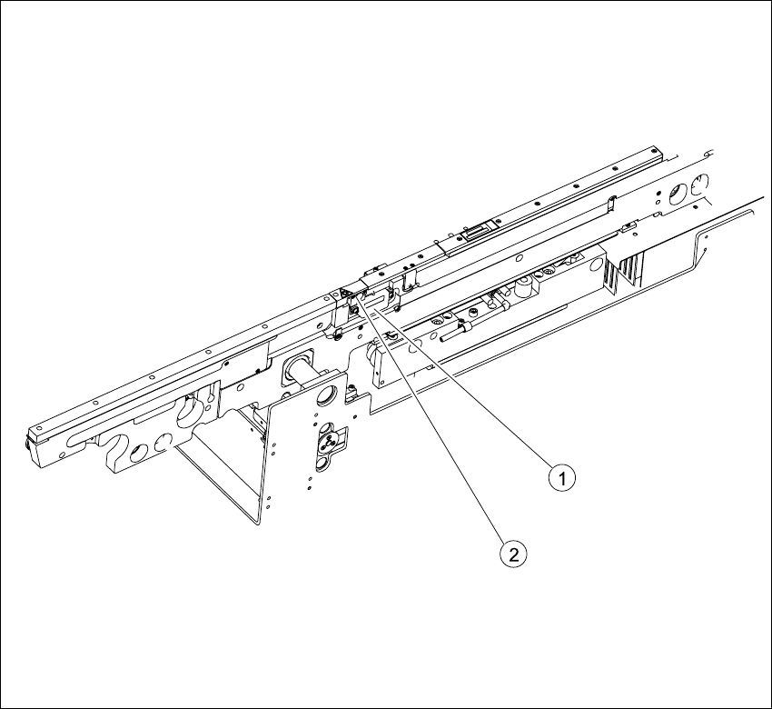
Fig. 6.14.30 Laser light barrier for stopper positions
Key
6.14.3.2 Parts
– 00364782-01 Laser light barrier for transmitter module BB1
– 00364782-01 Laser light barrier for transmitter module BB2
(1) Transmitter module (amplifier) with 2
screws
(2) Transmitter module (round laser diode)
with 3 screws