Service Manual HS60.pdf - 第309页
HS -60 Se rvic e Ma nual 7 DLM2 Co l lect&Plac e Head 03/ 2 003 U S Iss ue 7. 16 Re plac ing the sta r (003 4118 1-0 1) 307 Æ I nsert the ga uge pin again into the gauge for the star and into the hole in the segment,…

7 DLM2 Collect&Place Head HS-60 Service Manual
7.16 Replacing the star (00341181-01) 03/2003 US Issue
306
7.16.4 Fitting the star
PLEASE NOTE:
Remove any remaining sleeves before fitting the star.
Wear laboratory gloves when removing the sleeves. 7
Æ Push all the segments (item. 6 in Fig. 7.16 - 1) slightly outwards.
Æ Insert small Allen keys (e.g. size 2) into the holes for the star fixing screws (item 5 in Fig.
7.16 - 1
).
Æ Hold the star over the star drive shaft (item 3 in Fig. 7.16 - 1) so that the Allen keys slide into
the threaded holes in the star drive.
Æ Insert the star.
PLEASE NOTE:
Make sure that the vacuum hoses of the segments do not become squashed. 7
Æ Push all the segments inwards so that the segment ball bearings slide into the raceway (item
7 in Fig. 7.16 - 1
).
Æ Check that the star is seated flat on the drive shaft.
Æ Loosely tighten the three M3x8 hexagon socket head screws on the star so that the screws
can still move slightly in the fixing holes.
7.16.5 Adjusting the star with respect to the star's magnetic neutral position.
The aim of adjusting the star is to ensure that the vertical axis of segment no. 1 is aligned with the
magnetic neutral position of the star step motor. 7
Æ To do this, insert the gauge pin into the gauge for the star and into the hole in the segment
no. 1, until it reaches the stop.
Æ Pull off the motor line plug of the star motor from socket X5 on the intermediate distribution
board and connect the motor line to the power supply.
Æ Connect the power supply unit to main power.
Æ Tighten the three M3x8 hexagon socket head screws on the star.
Æ Remove the gauge pin.
HS-60 Service Manual 7 DLM2 Collect&Place Head
03/2003 US Issue 7.16 Replacing the star (00341181-01)
307
Æ Insert the gauge pin again into the gauge for the star and into the hole in the segment, until it
reaches the stop. Then check:
– that the gauge pin can be inserted easily.
– that the star does not rotate out of its current position as a result.
If both of these conditions are fulfilled, then the star has been fitted correctly. 7
Æ Disconnect the power pack from the power source.
Æ Continue from Section 7.6.3 "Fitting the front part of the collect&place head".
Æ Repeat the adjustment procedure if the gauge pin does not slide easily into the hole.
CAUTION
The maximum operating time of the power pack for the star motor is five minutes. Do NOT
exceed this time. If you have to disconnect the power pack from the power source because
it has been operating for five minutes, always insert the gauge pin before switching the power
pack on again. 7
If you still cannot fit the star in the magnetic neutral position of the star motor, follow the
instructions below: 7
Æ Loosen the four M5x16 hexagon socket head screws (item 2 in Fig. 7.16 - 2) for fixing the star
drive (item 1 in Fig. 7.16 - 2
) and turn the star drive in the direction that will allow the star to be
adjusted with respect to the magnetic neutral position. Tighten the four hexagon socket head
screws in this position.
7 DLM2 Collect&Place Head HS-60 Service Manual
7.16 Replacing the star (00341181-01) 03/2003 US Issue
308
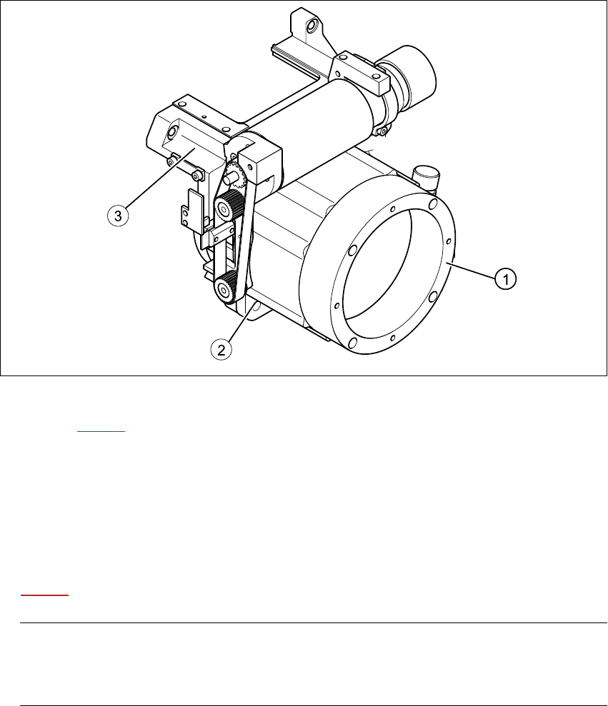
Fig. 7.16 - 2 Loosening the star drive
Key to Fig. 7.16 - 2
(1) Star drive, digital / DLM2
(2) M5x16 hexagon socket head screws, 4x
(3) Front part of collect&place head
7
Æ Loosen the three M3x8 hexagon socket head screws (item 5 in Fig.
7.16 - 1
) for fixing the star again and repeat the adjustment procedure.
PLEASE NOTE:
The star is fitted correctly until it no longer moves out of position when the gauge pin is
removed after disconnecting the star drive from the power supply. 7