Service Manual HS60.pdf - 第121页
HS -60 Se rvic e Manu al 4 Ga ntr ies 03/ 200 3 US I ssue 4. 11 R e plac in g the X- ax is m ot or un it ( 00 33 31 67- 03) 119 Æ T o slacken the toot hed belt (item 3 in F ig. 4.1 1 - 1 ) – loosen the locknut (item 8 in…
4 Gantries HS-60 Service Manual
4.11 Replacing the X-axis motor unit (00333167-03) 03/2003 US Issue
118
4.11 Replacing the X-axis motor unit (00333167-03)
4.11.1 Tools and equipment
– Set of DIN 911 Allen keys
–Cable ties
– TSM belt tension measuring device, from item number 00326015-01
– "Measuring belt tensions" operating instructions
4.11.2 Parts
X-axis motor unit, from item number 00333167-03 4
4.11.3 Removing the X-axis motor unit
Æ Switch the placement system off and secure it to prevent switching on again as described in
Section 4.4
, page 100 onward.
DANGER POWERFUL MAGNETIC FIELD 4
Always follow the special safety instructions when working in the vicinity of powerful magnetic
fields (see Section 4.5, page 101). 4
Gantry 1 or 3 4
Æ Remove the black cover strip on the cross-beam above the gantry concerned:
– Remove the fan cable from the socket. The fan is fixed to the black cover strip.
– Remove the black cover strip (3 M6x8 hexagon socket-head screws).
Æ Cut the cable ties holding the X-axis motor cable.
Æ Remove the cable clamp for the flat ribbon cable (item 11 in Fig. 4.11 - 1)
Æ Unplug all the plugs from the X/Y distributor (item 5 in Fig. 4.11 - 1).
Æ Remove the X/Y distributor (item 5 in Fig. 4.11 - 1).
Æ Remove the board holder for the X/Y distributor (item 9 in Fig. 4.11 - 1).
Æ Remove the cable holder (item 10 in Fig. 4.11 - 1) for the trailing cable.

HS-60 Service Manual 4 Gantries
03/2003 US Issue 4.11 Replacing the X-axis motor unit (00333167-03)
119
Æ To slacken the toothed belt (item 3 in Fig. 4.11 - 1)
– loosen the locknut (item 8 in Fig. 4.11 - 1
) and
– turn the hexagon socket-head screw counter-clockwise (item 2 in Fig. 4.11 - 1
).
Æ Loosen the two M6x14 socket head screws (item 7 in Fig. 4.11 - 1) for clamping the X-axis mo-
tor unit (item 4 in Fig. 4.11 - 1
).
Æ Pull the X-axis motor unit (item 4 in Fig. 4.11 - 1) up and out, at the same time pushing the
board holder slightly to the side.
4
Gantry 2 or 4 4
Æ Remove the black cover strip on the cross-beam above the gantry concerned:
– Remove the fan cable from the socket. The fan is fixed to the black cover strip.
– Remove the black cover strip (3 M6x8 hexagon socket-head screws).
Æ Cut the cable ties holding the X-axis motor cable.
Æ Remove the cable clamp for the flat ribbon cable (item 11 in Fig. 4.11 - 1)
Æ Unplug the X-motor plug from the X/Y distributor (item 5 in Fig. 4.11 - 1).
Æ Remove the board holder for the X/Y distributor (item 9 in Fig. 4.11 - 1).
Æ Remove the cable holder (item 10 in Fig. 4.11 - 1) for the trailing cable.
Æ To slacken the toothed belt (item 3 in Fig. 4.11 - 1)
– loosen the locknut (item 8 in Fig. 4.11 - 1
) and
– turn the hexagon socket-head screw counter-clockwise (item 2 in Fig. 4.11 - 1
).
Æ Loosen the two M6x14 socket head screws (item 7 in Fig. 4.11 - 1) for clamping the X-axis mo-
tor unit (item 4 in Fig. 4.11 - 1
).
Æ Pull the X-axis motor unit (item 4 in Fig. 4.11 - 1) up and out, at the same time pushing the
board holder slightly to the side.
4 Gantries HS-60 Service Manual
4.11 Replacing the X-axis motor unit (00333167-03) 03/2003 US Issue
120
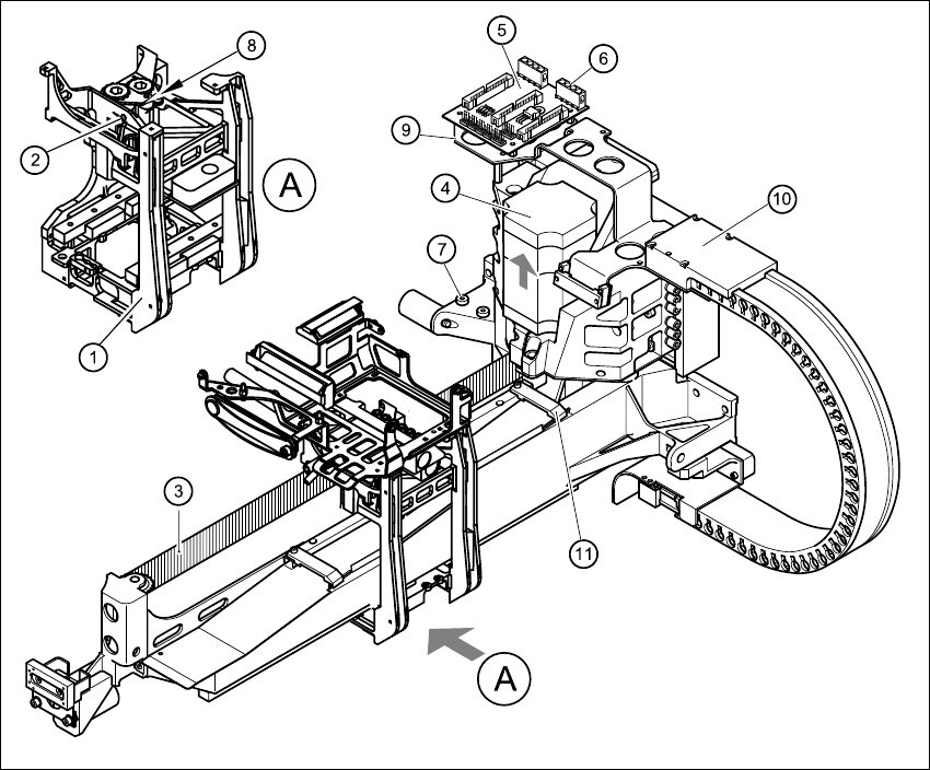
Fig. 4.11 - 1 Replacing the X-axis motor unit
Key
(1) Head mount
(2) M4 x 35 hexagon socket-head screw for tensioning the X-axis toothed belt
(3) Synchroflex X-axis toothed belt
(4) X-axis motor unit
(5) X/Y distributor
(6) X5 socket for X-axis motor
(7) 2 x M6 x 14 hexagon socket-head screws
(8) Locknut
(9) Board holder
(10) Cable holder
(11) Cable clamp