Service Manual HS60.pdf - 第251页
HS -60 Se rvic e Ma nual 7 DLM2 Co l lect&Plac e Head 03/ 2 003 U S Iss ue 7.1 Ov erv ie w 249 7.1. 2 Overview o f the functions of st ar st ations 1 - 12 7 F ig. 7. 1 - 2 Ov e rvi ew of the fu n ction s of s tar s t…

7 DLM2 Collect&Place Head HS-60 Service Manual
7.1 Overview 03/2003 US Issue
248
7.1.1 Steps when picking up and placing components
– A PCB moves into the placement area of the PCB conveyor.
– The right-hand collect&place head picks up components from the feeder modules.
– The left-hand collect&place head waits for the fiducial measurement.
– Once the fiducial measurement is complete, the right-hand collect&place head places compo-
nents while the left-hand collect&place head picks up further components.
– The right-hand collect&place head picks up components, and so on.
7.1.1.1 Position and function of the individual star stations (see Fig. 7.1 - 2)
Star station 1 7
Pick-up cycle 7
The nozzle is lowered onto the component. Once the valve positioning unit has opened the vac-
uum circuit to the nozzle, the nozzle draws up the component and removes it from the feeder mod-
ule. 7
Placement cycle 7
The valve positioning unit closes the vacuum channel to the nozzle. The nozzle, together with the
component, is lowered onto the PCB that has been moved into place. A short burst of compressed
air detaches the component from the nozzle and places it on the PCB. 7
Star station 3 7
The valve positioning unit closes the vacuum channel to the nozzle. Defective components are
detached from the nozzle with a short burst of compressed air and are discarded. 7
Star station 7 7
The component is optically centered. 7
Star station 9 7
Pick-up cycle 7
The nozzle is rotated to the pick-up position. 7
Placement cycle 7
The placement angle of the component is corrected or the correct placement angle of the compo-
nent is set. 7
HS-60 Service Manual 7 DLM2 Collect&Place Head
03/2003 US Issue 7.1 Overview
249
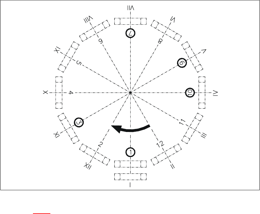
7.1.2 Overview of the functions of star stations 1 - 12
7
Fig. 7.1 - 2 Overview of the functions of star stations 1 - 12
Key to Fig. 7.1 - 2
Star station 1:pick up or place component 7
Star station 2:no function 7
Star station 3:discard component 7
Star station 4, 5 and 6:no function 7
Star station 7:optically center component 7
Star station 8:no function 7
Star station 9:rotate component 7
Star station 10:position for removing and inserting sleeves 7
Star stations 11 and 12:no function 7
I-XIISegment numbering 7
7 DLM2 Collect&Place Head HS-60 Service Manual
7.2 Structure of the collect&place head 03/2003 US Issue
250
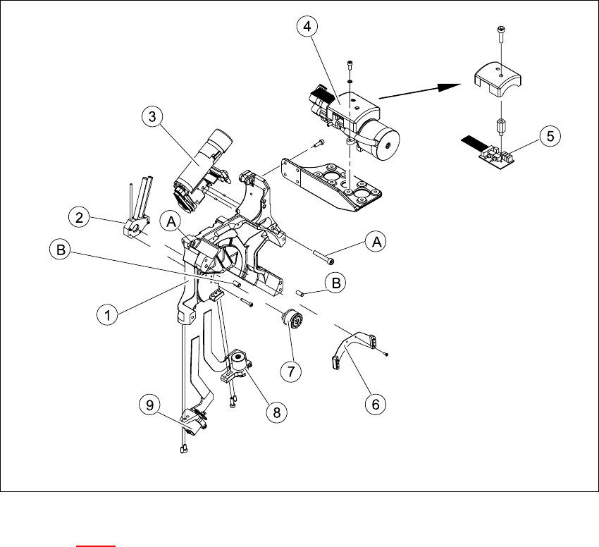
7.2 Structure of the collect&place head
7.2.1 Back part, complete / DLM2
The back part of the collect&place head is fixed to the head mount on the gantry with three M4x16
hexagon socket-head screws (item A). Two parallel pins (item B) are used to center the front part
of the collect&place head. 7
Fig. 7.2 - 1 Structure of the back part, complete / DLM2
Key to Fig. 7.2 - 1
(1) Back part / DLM2 (2) Vacuum distributor
(3) Turning station (4) Vacuum generator / DLM2
(5) SP6 / 12 vacuum measurement board (6) Brake for star
(7) Distributor piece (8) "Placement circuit" valve positioning drive
(9) "Reject circuit" valve positioning drive 7