Service Manual HS60.pdf - 第145页
Se rv ice M a nu al HS- 6 0 5 P ne um at ic Cu tte r an d Em pt y-T ap e D uc t 03/ 200 3 U S Iss ue 5. 6 C h angi ng of pa rts 143 5.6. 2.1 Inst a lling t he arti culated joint and short -stroke cy linder W ARNING Y ou …
5 Pneumatic Cutter and Empty-Tape Duct Service Manual HS-60
5.6 Changing of parts 03/2003 US Issue
142
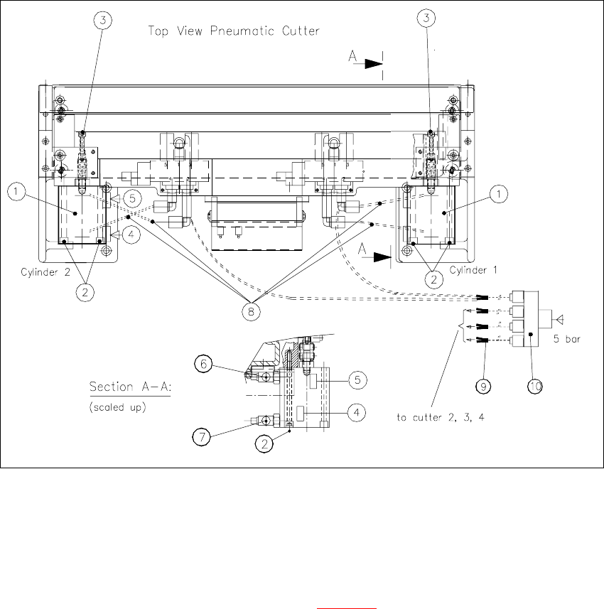
Fig. 5.6.3 Removing and Installing the Short-Stroke Cylinder
Key:
1. Short-stroke cylinders 1 and 2
2. Screws fastening the short-stroke cylinders: 2 socket hex head cap screws each, M5 x 65
3. Screws fastening the articulated joint (see also Fig. 5.6.4
)
4. Proximity switch (for position cylinder moved in). Fastener: 1 cross-slotted screw
5. Proximity switch (for position cylinder moved out). Fastener: 1 cross-slotted screw
6. One-way restrictor (for running cylinder out)
7. One-way restrictor (for running cylinder in)
8. Allocation of the compressed air connections, air hoses
9. Y-socket union (in the cable pit)
10. Multiple-Y-distributor on the safety valve (5 bar from compressed air unit)
Service Manual HS-60 5 Pneumatic Cutter and Empty-Tape Duct
03/2003 US Issue 5.6 Changing of parts
143
5.6.2.1 Installing the articulated joint and short-stroke cylinder
WARNING
You might cut yourself on the blades and the tape deflector. 5
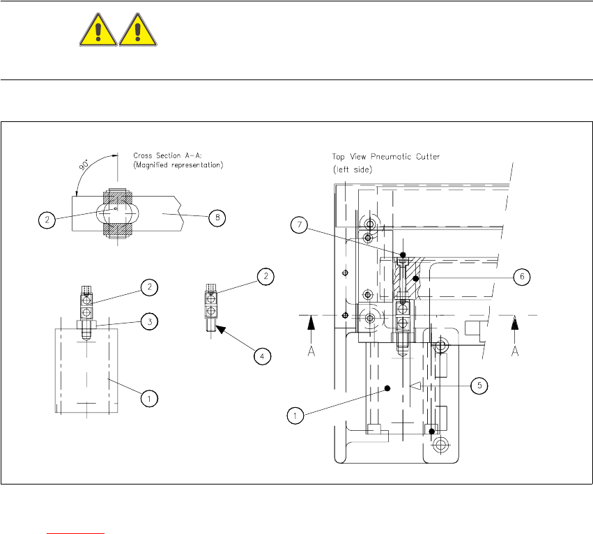
Fig. 5.6.4 Removing Articulated Joint, Installing It on New Master Cylinder and Bonding It in Place
Key to Fig. 5.6.4 (right):
1. Short-stroke cylinder (1 or 2)
2. Articulated joint (complete)
3. Wrench surface for disassembling the articulated joint
4. Secure articulated joint thread with Loctite no. 243
5. Open-end wrench surface of articulated joint
6. Slide surface of the movable blade
7. Screw fastening the articulated joint to the movable blade:
one M4 x 24 DIN 912 socket hex head cap screw each, strength 12.9, secured with Loctite no.
243
5 Pneumatic Cutter and Empty-Tape Duct Service Manual HS-60
5.6 Changing of parts 03/2003 US Issue
144
8. Movable blade with slot to prevent the articulated joint from turning if the articulated joint is
damaged, use a (complete) new one (Item no.: see Section 5.2
) or clean the residues of Loctite
from the thread of the existing articulated joint pin.
CAUTION
Tighten the screws to the correct torque -> see Table, Fig. 5.4.2. 5
Æ Apply a small amount of Loctite no. 243 (Item no.: see Section 5.3) to the thread.
Æ Take note of the following WARNING. If the enamel on the one-way restrictor is damaged use
a new "short-stroke cylinder".
DANGER
One-way restrictors are not to be set on the machine. This is only permitted at the factory.
For this reason the replacement short-stroke cylinder must always be installed, together with the
new, already adjusted restrictors attached to it. 5
Æ Screw the articulated joint into the short-stroke cylinder.
Æ Turn the articulated joint into the mounting position (see Fig. 5.6.4, diagram on the left).
Once the cylinder is installed, the slot in the moveable blade prevents the articulated joint from
turning.
Æ Copy the exact mounting position of the proximity switch to the short-stroke cylinder (feeler
gauge, fine-tip marker).
Æ Install the prepared cylinder - complete with one-way restrictors - on the cutter, in the correct
rotational position for the articulated joint.
Æ Fasten the cylinder in this position with the 2 screws M5x65 (Fig. 5.6.3 -> 2) provided.
Æ Install the proximity switch (article no. see Section 5.2) precisely in the position you marked on
the short-stroke cylinder with the permanent marker (see Fig. 5.6.3
-> 4, 5).
Æ Connect the compressed air hoses to the one-way restrictor on the cylinder, in the correct al-
location (see markings). For allocation details please refer to Fig. 5.4.2
-> 6, 7, 8.
Æ Perform the following steps as described in Section 5.6.2.1:
Æ Fasten the moveable blade to the articulated joint.
Æ Re-install the empty-tape duct on the machine frame (2 screws each on LH and RH, see Fig.
5.4.1 -> 6, 9).
Æ Check the gap between the leading edge of the tape deflector and the "empty-tape baffle, in-
side", as described in Section 5.6.6
.
Æ Check the switching points of the proximity switches, as described in Section 5.6.5.