Service Manual HS60.pdf - 第59页
Se rv ice M a nu al HS-6 0 2 Ope rati on al saf et y 03/ 2003 US Is sue 2.7 Ener gy sta te of the mach ine a fte r swit chin g off at t h e main powe r swit ch 57 2.7 Energy st ate of t he machi ne af ter switc hing off …
2 Operational safety Service Manual HS-60
2.6 Disabling the compressed air supply and discharging the pressure 03/2003 US Issue
56
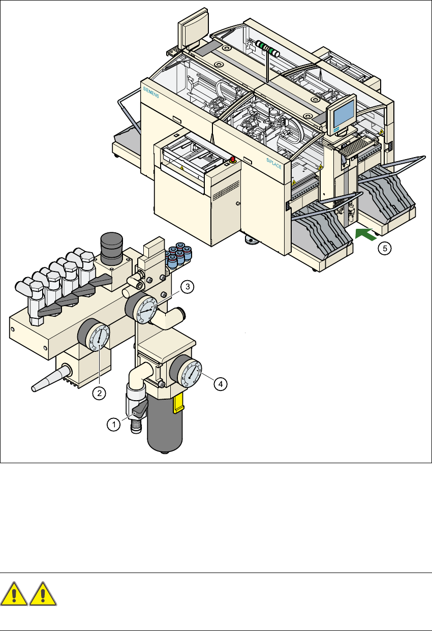
Fig. 2.6 - 1 Compressed air unit on the automatic placement system
WARNING
NEVER detach compressed air lines while they are still pressurized. Risk of injury. 2
(1) Shutoff valve lever in the CLOSED position
(2) Working pressure gauge
(3) Pressure gauge for the component table operating pressure
(4) Input pressure gauge
(5) Position of the compressed air unit on the placement system behind the safety door
Service Manual HS-60 2 Operational safety
03/2003 US Issue 2.7 Energy state of the machine after switching off at the main power switch
57
2.7 Energy state of the machine after switching off at
the main power switch
WARNING 2
The placement system is supplied with 3 x 204 VAC (US version), 3 x 230 VAC, 3 x 380 VAC,
3 x 400 VAC or 3 x 415 VAC ± 5 %, 50/60 Hz main power voltage. This means that some parts of
the system carry potentially lethal voltages - even when switched off at the main power
switch.Death, serious injury or considerable damage may result if this automatic placement sys-
tem is handled incorrectly.
Æ Always follow the applicable accident prevention and DIN regulations (particularly DIN EN 60
204, part 1).
Æ The guard over the servo unit must ONLY be opened by appropriately qualified and trained
personnel.
2 Operational safety Service Manual HS-60
2.7 Energy state of the machine after switching off at the main power switch 03/2003 US Issue
58
2
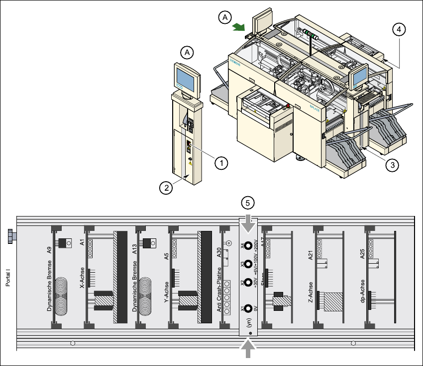
Fig. 2.7 - 1 Position of the servo unit, main power switch, service socket, and compressed air unit
in the placement system
2
(1) Main power switch
(2) Service socket behind the safety door
(3) Compressed air unit
(4) Servo unit
(5) Measuring unit in the servo unit