Service Manual HS60.pdf - 第297页
HS -60 Se rvic e Ma nual 7 DLM2 Co l lect&Plac e Head 03/ 2003 US Issu e 7.12 R epl acin g the to othe d bel t of t he Z- axis (003 3493 6-01) 295 7 Fig. 7.1 2 - 2 Loose ning the Z -axi s dri ve Ke y to Fi g. 7.12 - …
7 DLM2 Collect&Place Head HS-60 Service Manual
7.12 Replacing the toothed belt of the Z-axis (00334936-01) 03/2003 US Issue
294
7
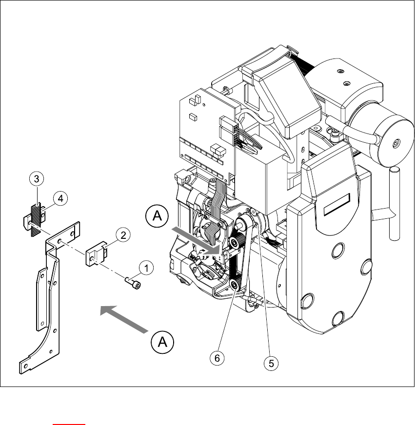
Fig. 7.12 - 1 Replacing the toothed belt for the Z-axis
Key to Fig. 7.12 - 1
(1) 2 x M2.5x8 hexagon socket-head screw
(2) Stop
(3) Toothed belt for the Z-axis
(4) Tension jack
(5) Z-axis drive
(6) 2 x deflection wheel / DLM2
HS-60 Service Manual 7 DLM2 Collect&Place Head
03/2003 US Issue 7.12 Replacing the toothed belt of the Z-axis (00334936-01)
295
7
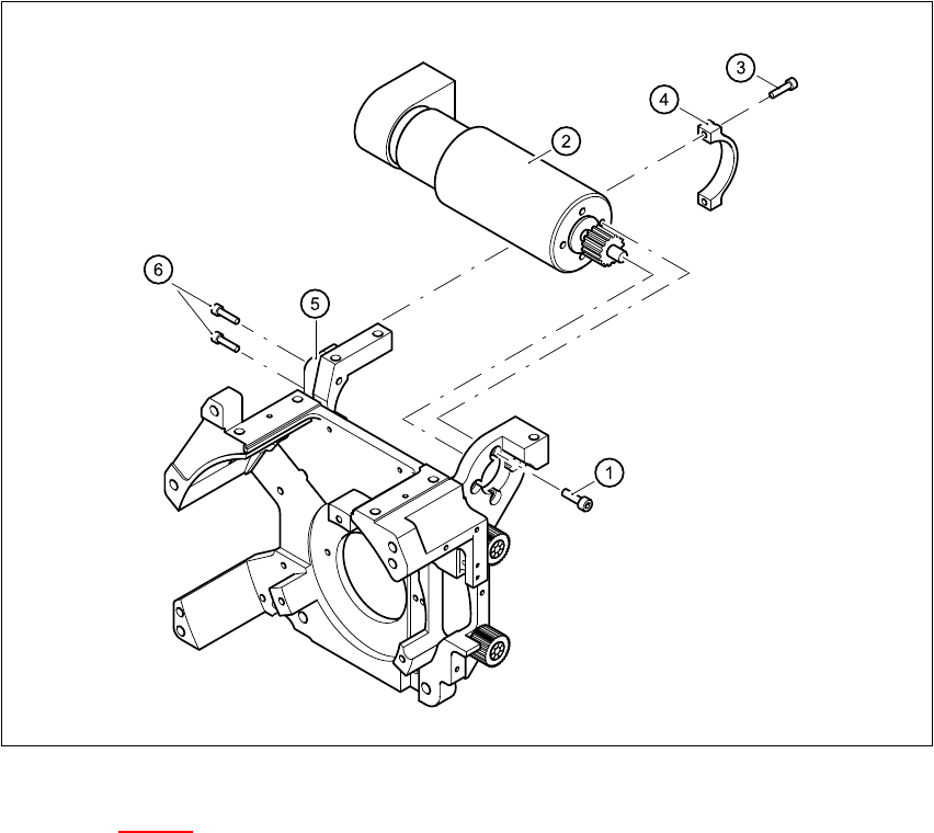
Fig. 7.12 - 2 Loosening the Z-axis drive
Key to Fig. 7.12 - 2
(1) 4 x M3x5 hexagon socket-head screw with locking varnish
(2) Z-axis drive
(3) 2 x M2.5x12 hexagon socket-head screw
(4) Motor clamp fitting 2 / DLM2
(5) Motor clamp fitting / DLM2
(6) 2 x M3x14 hexagon socket-head screw
7
7 DLM2 Collect&Place Head HS-60 Service Manual
7.12 Replacing the toothed belt of the Z-axis (00334936-01) 03/2003 US Issue
296
7.12.4 Fitting the toothed belt T2 / DLM2
Æ Place the new toothed belt over the pinion of the Z-axis drive and the deflection wheels.
PLEASE NOTE 7
Make sure that the teeth of the toothed belts engage in the teeth of the pinion and deflection pul-
leys. 7
Æ Use the two M2.5x8 hexagon socket-head screws (item 1 in Fig. 7.12 - 1) to fix the stop (item 2
in Fig. 7.12 - 1
) and the tension jack (item 4 in Fig. 7.12 - 1) to the toothed belt.
Æ Make sure that both ends of the turnbuckle come to lie on the ends of the toothed belt.
Æ Lightly tighten the four M3x5 hexagon socket head screws (item 1 in Fig. 7.12 - 2) on the
Z drive unit.
Æ Tension the Z toothed belt by pushing the Z drive unit upwards.
7.12.5 Settings
Æ Use the belt tension measuring device to check the tension of the toothed belt (see setting in-
structions).
Æ Tighten the two M3x14 hexagon socket-head screws (item 6 in Fig. 7.12 - 2) for fixing the mo-
tor clamp (item 5 in Fig. 7.12 - 2
).
Æ Tighten the two M2.5x12 hexagon socket-head screws (item 3 in Fig. 7.12 - 2) for fixing the
motor clamp 2 (item 4 in Fig. 7.12 - 2
).
PLEASE NOTE:
Now tighten the hexagon socket head screws on the Z-drive unit and the motor clamps. 7
7
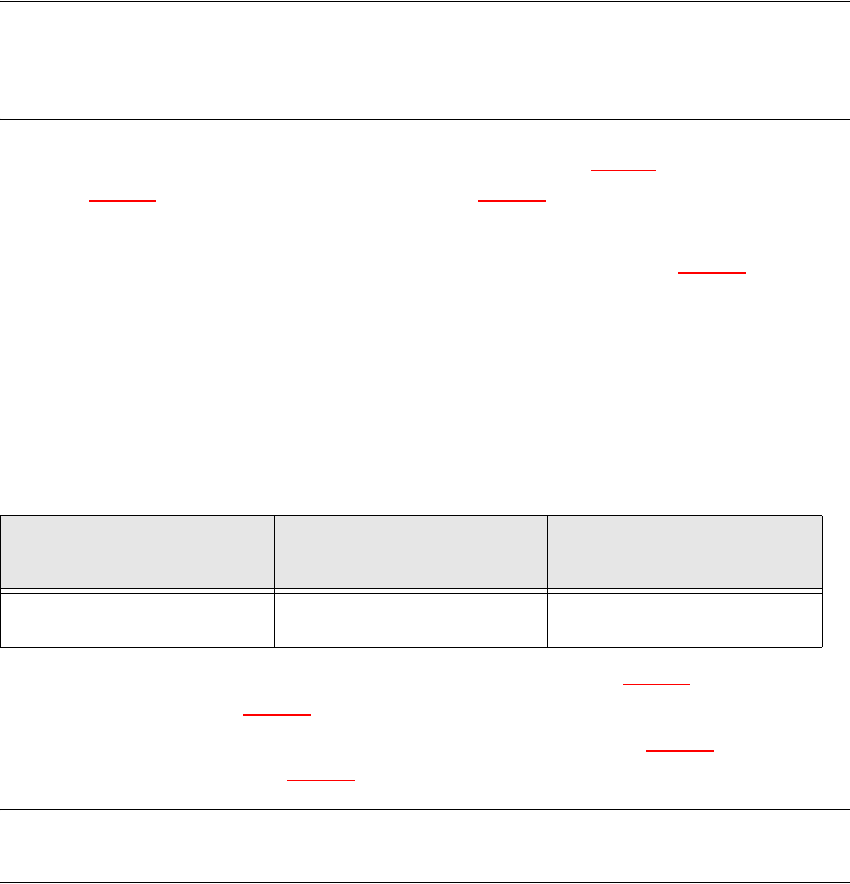
Frequency (Hz)
before continuous operation
Frequency (Hz)
after continuous operation
Toothed belt T2 / DLM2
on the Z-axis 280 ± 10 280 ± 10