Service Manual HS60.pdf - 第270页
7 DL M2 Co llec t &P lace Head H S-6 0 S erv ic e Manu al 7. 5 R ep la cing th e c o lle c t&p la ce h ead / DLM 2 ( 0 0367 77 0-0 1) 03/ 2 003 U S I ss ue 268 Æ M ake sure that the plugs are fi rm ly locked in p…
HS-60 Service Manual 7 DLM2 Collect&Place Head
03/2003 US Issue 7.5 Replacing the collect&place head / DLM2 (00367770-01)
267
7.5.4 Fitting the collect&place head on the head mount
7
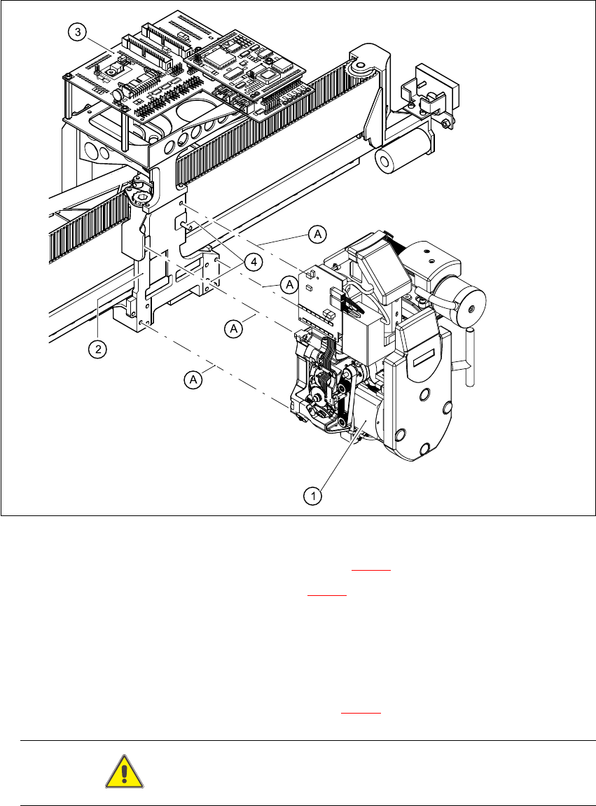
Fig. 7.5 - 4 Fitting the collect&place head
Æ Carefully move the collect&place head (item 1 in Fig. 7.5 - 4) onto the head mount (2).
Æ Make sure that the parallel pins (item 4 in Fig. 7.5 - 4) on the head mount slide into the holes
in the back part of the collect&place head.
Æ Carefully push the collect&place head towards the head mount until it is lying flat.
Æ Use four M4x16 hexagon socket-head screws to fix the collect&place head (A).
Æ Connect the plugs for the collect&place head to the head board.
The plug positions and assignment is shown in Fig. 7.5 - 1
.
CAUTION Check the polarity of the plugs before connecting. 7

7 DLM2 Collect&Place Head HS-60 Service Manual
7.5 Replacing the collect&place head / DLM2 (00367770-01) 03/2003 US Issue
268
Æ Make sure that the plugs are firmly locked in place.
Æ Check that the plugs of the 40-pin ribbon cables between the intermediate distribution board
and head board are correctly assigned:
Æ Make sure that the cables are not damaged and that there is no strain on the connecting ca-
bles.
Æ Connect the compressed air hoses.
7.5.5 Settings
Æ Close the protective cover.
Æ Check that you have removed all tools and equipment from inside the placement system.
Æ Start the placement system.
Æ Use the SITEST program to calibrate the collect&place head.
Cable Head board Intermediate distribution board
00333491-W1 X14 X1
00333491-W2 X13 X2
Tab. 7.5 - 2 Plug-in connections for the flat ribbon cables on the head board
HS-60 Service Manual 7 DLM2 Collect&Place Head
03/2003 US Issue 7.6 Dismantling / fitting the front part of the collect&place head
269
7.6 Dismantling / fitting the front part of the
collect&place head
7.6.1 Tools and equipment
– Set of DIN 911 Allen keys
– SITEST program
– Adjustment instructions
CAUTION Be careful with the glass scales in the sleeves. They are very fragile. 7
7.6.2 Dismantling the front part of the collect&place head
Æ Switch the placement system off and secure it to prevent switching on again as described in
Section 7.4
, page 261.
Æ Remove the connecting cable plugs from sockets X9, X13, X14 on the head board
(see Fig. 7.5 - 1
).
Æ Remove the pneumatic hose.
Æ Undo the four M3x16 hexagon socket head screws (item A in Figs. 7.6 - 1 and 7.6 - 2).
CAUTION When you undo the last screw, hold the collect&place head so that it
does not accidentally drop off the back part. 7
CAUTION When you remove the front part of the collect&place head, make sure
that the star is pivoted roughly 15° away from the vertical sleeve position. Otherwise the valve
plunger will remain attached to the valve actuator. 7
Æ Lift the front part of the collect&place head away from the parallel pins on the back part and
place on a soft, clean surface.