Service Manual HS60.pdf - 第84页
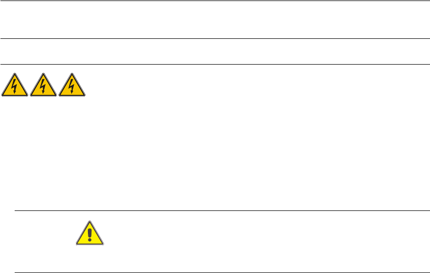
3 Pow er S up ply H S-6 0 S erv ic e Manu al 3. 7 M e as ur ing vol ta ge s on th e p o wer su pp ly unit 03/ 200 3 US I ssue 82 3 F ig. 3. 7 - 3 P rim ary t erm inal s of tra ns fo rm er T 1 3.7. 6.2 Secondary s ide of …
HS-60 Service Manual 3 Power Supply
03/2003 US Issue 3.7 Measuring voltages on the power supply unit
81
PLEASE NOTE: Remember to replace the perspex safety panels over rectifiers V1 and V7
when the measurements are complete. 3
RISK OF DEATH BY ELECTRIC SHOCK 3
Æ Switch the placement system off at the main switch.
Æ Disconnect the placement system from the power supply.
Æ Wait approximately 1 minute until the residual voltages have dropped to a safe level (electro-
lytic capacitor C1).
Æ Attach the perspex safety panel and fix in place with the M5 fillister head screws.
CAUTION
Do not overtighten the fillister head screws. The perspex panel might break. 3
3.7.6 Measuring voltages at transformer T1
3.7.6.1 Primary side of transformer T1
The transformer can be connected to the following main power supplies: 3
3 x 230 VAC for the "on-board electrical system" is drawn at terminals 1U5, 1V5 and 1W5. This is
used to supply the PC and the monitor. 3
3
Voltage Terminals
3 x 204 VAC (U. S. A.) ± 5 %, 50/60 Hz 1U6, 1V6, 1W6
3 x 230 VAC ± 5 %, 50/60 Hz 1U5, 1V5, 1W5
3 x 380 VAC ± 5 %, 50/60 Hz 1U4, 1V4, 1W4
3 x 400 VAC (Europe) ± 5 %, 50/60 Hz 1U3, 1V3, 1W3
3 x 415 VAC ± 5 %, 50/60 Hz 1U1, 1V1, 1W1
3 Power Supply HS-60 Service Manual
3.7 Measuring voltages on the power supply unit 03/2003 US Issue
82
3
Fig. 3.7 - 3 Primary terminals of transformer T1
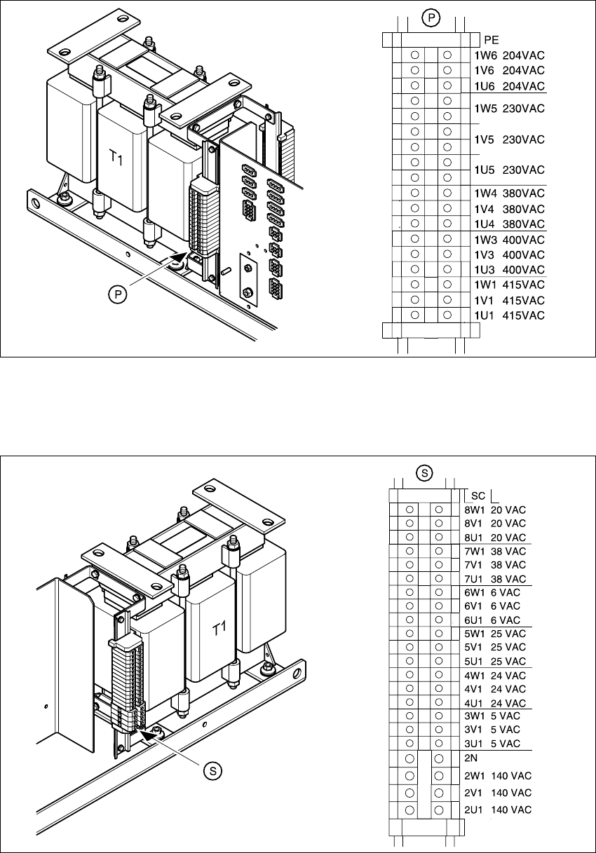
3.7.6.2 Secondary side of transformer T1
3
Fig. 3.7 - 4 Secondary terminals of transformer T1
HS-60 Service Manual 3 Power Supply
03/2003 US Issue 3.7 Measuring voltages on the power supply unit
83
Transformer T1 supplies the following voltages on the secondary side: 3
– 3 x 140 VAC
–3 x 5 VAC
– 3 x 24 VAC
– 3 x 25 VAC
–3 x 6 VAC
– 3 x 38 VAC
–3 x 20 VAC
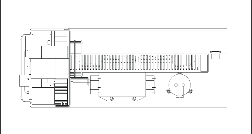
3.7.7 Measuring voltages at main power filter Z1 and electrolytic capacitor C1
Fig. 3.7 - 5 Power supply unit - plan view
Z1 Main power filter for 36 A 3-phase systems
E Input terminals of main power filter Z1
A Output terminals of main power filter Z1
C1 33000 µF / 63 V electrolytic capacitor
R1 Discharge resistor
Module Terminal Voltages
Main power filter Z1 L1, L2, L3 3 x 204 VAC / 3 x 230 VAC / 3 x 380 VAC
3 x 400 VAC / 3 x 415 VAC
Electrolytic capacitor C1 + / - 52 VDC
R1
C1
Z1
+
-
L1
L2
PE
L3
AE
PE
L3
L2
L1