Service Manual HS60.pdf - 第262页
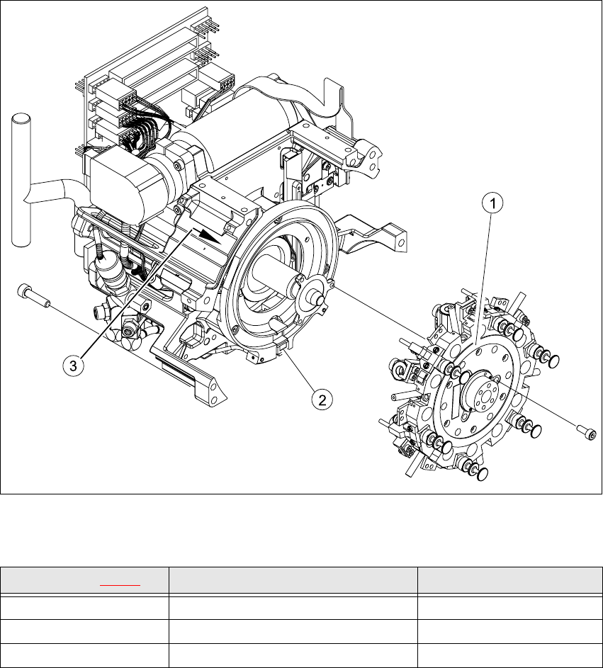
7 DL M2 Co llec t &P lace Head H S-6 0 S erv ic e Manu al 7. 3 P art s ov erv ie w 0 3/2 003 U S I ssue 260 7 Fig . 7.3 - 3 DLM2 col lect &pl ace he ad - pa rt s over view 3 It em i n Fig . 7.3 - 3 Designa tion I…
HS-60 Service Manual 7 DLM2 Collect&Place Head
03/2003 US Issue 7.3 Parts overview
259
7
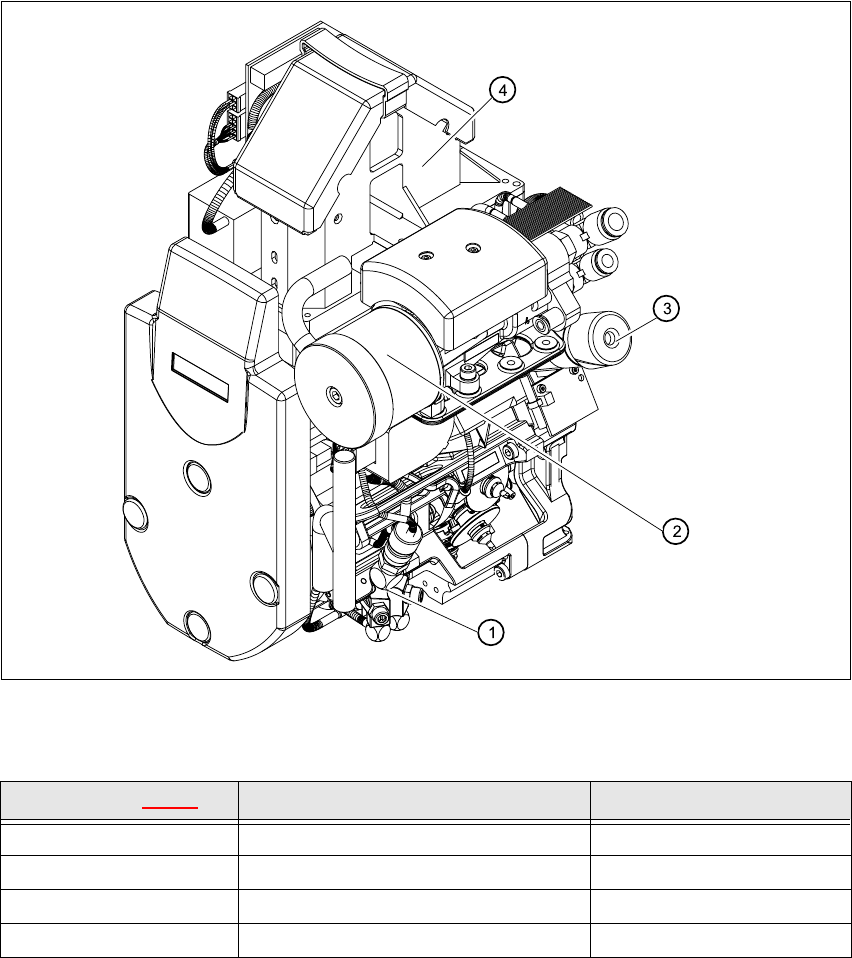
Fig. 7.3 - 2 DLM2 collect&place head - parts overview 2
Item in Fig. 7.3 - 2 Designation Item no.
1 Forced air unit / DLM2 00367793-01
2 Silencer 03003134-01
3 Turning station / DLM2 00341780-03
424x24 component camera KST 00336791-03
HS-60 Service Manual 7 DLM2 Collect&Place Head
03/2003 US Issue 7.4 Points to note before starting servicing work ...
261
7.4 Points to note before starting servicing work ...
Æ End all placement operations on the placement system.
Æ Switch the placement system off at the main switch.
Æ Wait, until the operating system has shut down and the UPS has switched off.
Æ Disconnect the placement system from the power supply.
Æ Disconnect the placement system from the compressed air supply.
Æ Switch off the motor contactor in the power supply unit and secure the operating lever with a
padlock.
7
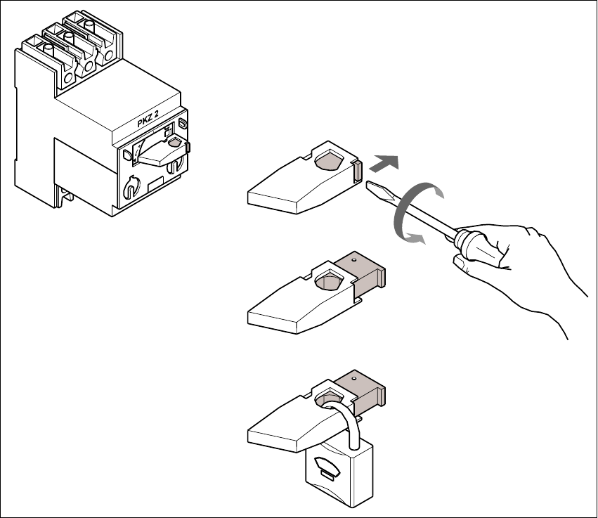
Fig. 7.4 - 1 Locking the motor contactor
(1) Turn the operating lever (1) counter-clockwise.
(2) Use the screwdriver to push the locking lug (2) out of the operating lever (1).
(3) Secure the operating lever with a padlock (3).