Service Manual HS60.pdf - 第125页
HS -60 Se rvic e Manu al 4 Ga ntr ies 03/ 2003 US Issu e 4.1 2 Repla ci ng th e lin ear m otor - prim ary par t (003 3314 8-0 2) 123 4.12 Repla cing the linear motor - primary part (003331 48-02) 4.12.1 T ools an d equip…
4 Gantries HS-60 Service Manual
4.11 Replacing the X-axis motor unit (00333167-03) 03/2003 US Issue
122
CAUTION 4
Make sure that the cables are firmly seated. Otherwise, the high acceleration forces may
cause the cable to slip out of position and shear through. 4
Æ Turn the hexagon socket-head screw (item 2 in Fig. 4.11 - 1) to pre-tension the X-axis toothed
belt.
Æ Use the three M6 x 8 hexagon socket-head screws to fit the black cover strip to the cross-beam
above the gantry concerned.
Æ Connect the cable of the fan motor to the socket.
4.11.5 Settings
Æ Push the head mount (item 1 in Fig. 4.11 - 1) towards X-axis motor unit as far as the stop on
the elastomeric spring.
Æ Turn the hexagon socket-head screw (item 2 in Fig. 4.11 - 1) to set the belt tension to
53 Hz + 1/-3 Hz.
CAUTION 4
Do not overstretch the toothed belt when adjusting the belt tension. 4
Æ Secure the hexagon socket-head screw (item 2 in Fig. 4.11 - 1) with the locknut (item 8 in Fig.
4.11 - 1
).
HS-60 Service Manual 4 Gantries
03/2003 US Issue 4.12 Replacing the linear motor - primary part (00333148-02)
123
4.12 Replacing the linear motor - primary part
(00333148-02)
4.12.1 Tools and equipment
– Set of DIN 911 Allen keys
–Cable ties
– TSM belt tension measuring device, from item number 00326015-01
– "Measuring belt tensions" operating instructions
4.12.2 Parts
Linear motor - primary part, from item number 00333148-02 4
4.12.3 Removing the permanent magnets
Æ Switch the placement system off and secure it to prevent switching on again as described in
Section 4.4
, page 100 onward.
DANGER POWERFUL MAGNETIC FIELD 4
Always follow the special safety instructions when working in the vicinity of powerful magnetic
fields (see Section 4.5, page 101 onward). 4
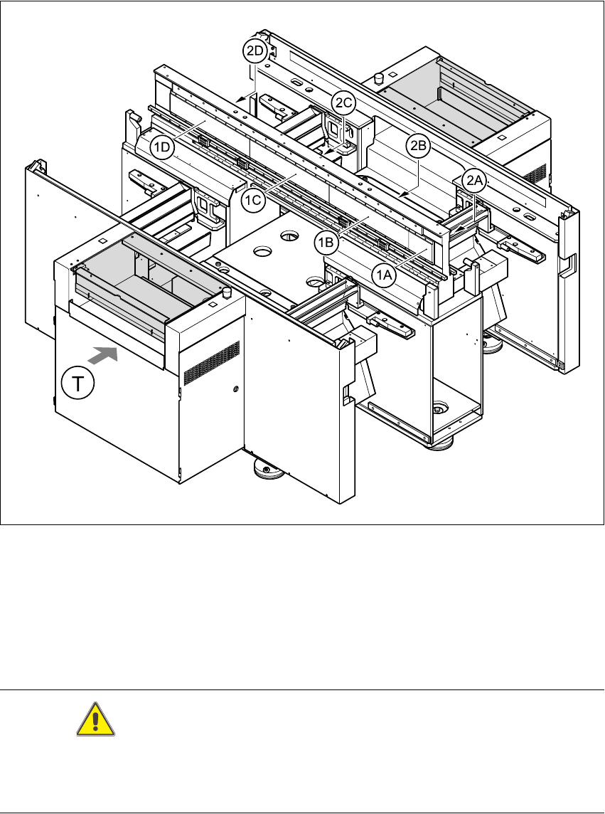
Æ Move the gantry in the PCB transport direction and position it so that the permanent magnets
can be removed:
– For gantry 1, position above the permanent magnets, item 1C in Fig. 4.12 - 1
– For gantry 2, position above the permanent magnets, item 2C in Fig. 4.12 - 1
– For gantry 3, position above the permanent magnets, item 2C in Fig. 4.12 - 1
– For gantry 4, position above the permanent magnets, item 1C in Fig. 4.12 - 1
Æ Remove the black cover strips on the cross-beam above the gantry concerned (3 M6 x 8 hex-
agon socket-head screws)
4 Gantries HS-60 Service Manual
4.12 Replacing the linear motor - primary part (00333148-02) 03/2003 US Issue
124
Fig. 4.12 - 1 Position of the permanent magnets of the Y-axis linear drives
Key
1A, 1B, 1C, 1DPermanent magnets for the Y-axis linear drive for gantries 1 and 4 4
2A, 2B, 2C, 2DPermanent magnets for the Y-axis linear drive for gantries 2 and 3 4
T Transport direction 4
CAUTION
When permanent magnets are placed on a magnetic surface (e.g. iron, nickel or steel), be ex-
tremely careful not to catch your hands or fingers between the surface and the permanent magnet.
If you do, you will not be able to lift the magnet from the surface on your own. 4