Service Manual HS60.pdf - 第54页
2 O per ati onal sa fety S er vice Ma nual H S- 60 2.4 S afe ty equi pment 03/ 200 3 U S Iss ue 52 2.4. 5 Gu ard on the co m pon ent t able locatio ns DANGER 2 All locations must be equipped with feeders in order to guar…
Service Manual HS-60 2 Operational safety
03/2003 US Issue 2.4 Safety equipment
51
2
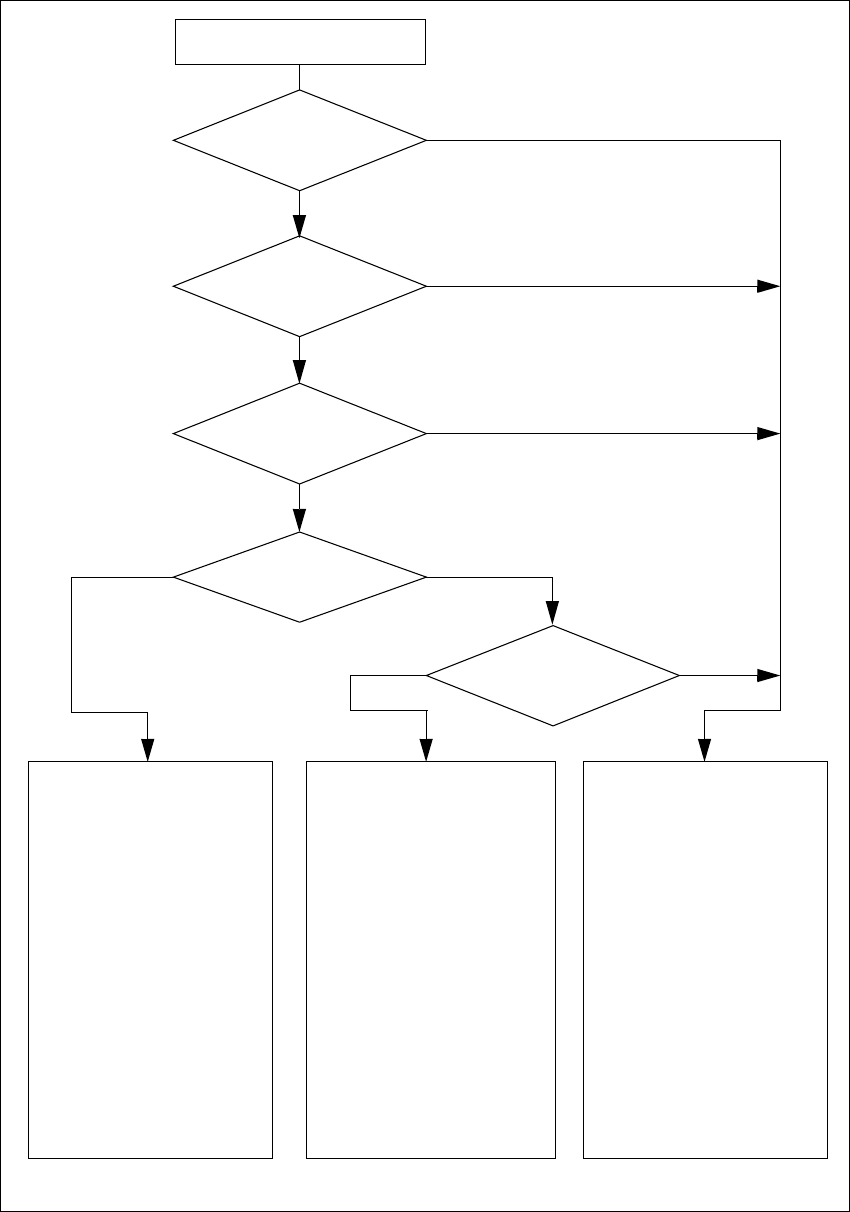
Fig. 2.4 - 7 Safety circuits
Compressed air
min. 0.5 MPa
(5.0 bar)?
No
Start button pressed
Emerg. stop
mushroom-head push-but-
ton pressed?
Protective cover open ?
Key switch
closed (positionI)?
No
Component table
safety circuit
interrupted?
Yes
No
No
Yes
Yes
No
Active
PCC*) yes
voltage
Y-axis 200 V
X-axis 200 V
Star axis 100 V
DP-axis 30 V
Z-axis 30 V
Active
PCB conveyor yes
Lifting table yes
PCB clamping yes
Width adjustment yes
Laser light barrier yes
Used tape cutter yes
Yes
Active
PCC*) no
voltage
Y-axis 0 V
X-axis 0 V
Star axis 6 V
DP-axis 30 V
Z-axis 30 V
Active
PCB conveyor yes
Lifting table no
PCB clamping no
Width adjustment yes
Laser light barrier no
Used tape cutter no
Active
PCC*) no
voltage
Y-axis 0 V
X-axis 0 V
Star axis 10 V
DP-axis 30 V
Z-axis 30 V
Active
PCB conveyor no
Lifting table no
PCB clamping no
Width adjustment no
Laser light barrier no
Used tape cutter no
*) PCC protective contactor combination
yes
2 Operational safety Service Manual HS-60
2.4 Safety equipment 03/2003 US Issue
52
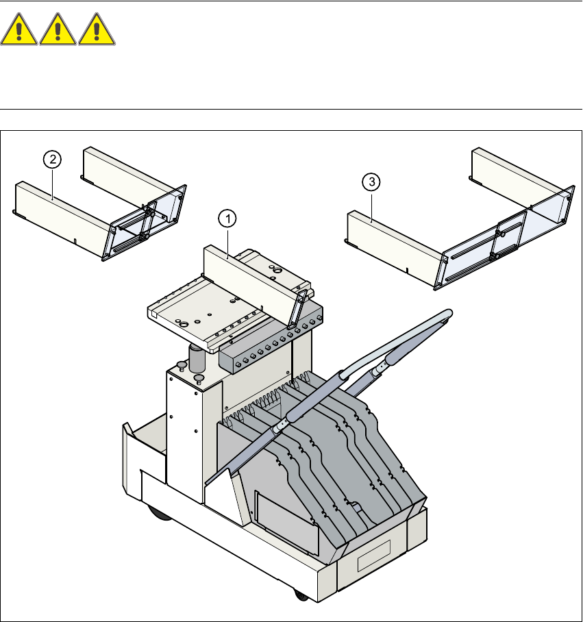
2.4.5 Guard on the component table locations
DANGER 2
All locations must be equipped with feeders in order to guarantee operational reliability.If there
are not enough feeders available, a guard ("dummy feeder") must be fitted in place of the feeder.
Fig. 2.4 - 8 Guard on the CO trolley
(1) Guard for 1 location item no. 00116820-01
(2) Guard for 6 to 10 locations item no. 00116821-01
(3) Guard for 11 to 20 locations item no. 00116822-01
Service Manual HS-60 2 Operational safety
03/2003 US Issue 2.5 Residual voltages and discharge times in the machine
53
2.5 Residual voltages and discharge times in the
machine
If the EMERGENCY-STOP mushroom-head push-button is pressed or the placement system is
switched off, the 200 V link voltage for the gantry axes and the 100 V link voltage for the star axes
are discharged to harmless residual voltages in a very short time.
The voltages can be tapped off at test sockets X1 - X4 on the voltage measuring unit in the servo
unit. 2
WARNING 2
The placement system is supplied with 3 x 204 VAC (US version), 3 x 230 VAC, 3 x 380 VAC,
3 x 400 VAC or 3 x 415 VAC ± 5 %, 50/60 Hz main power voltage. This means that some parts of
the system carry potentially lethal voltages - even when switched off at the main power
switch.Death, serious injury or considerable damage may result if this automatic placement sys-
tem is handled incorrectly.
Æ Always follow the applicable accident prevention and DIN regulations (particularly DIN EN 60
204, part 1).
Æ The guard over the servo unit must ONLY be opened by appropriately qualified and trained
personnel.